Electrolytic machining device and method for a deep special-shaped hole

A technology of processing device and electrolytic machining machine tool, which is applied in the direction of electric processing equipment, supply of processing working medium, accessories, etc., can solve deep special-shaped holes, deep concave cavity movement is not free enough, processing depth is not enough, prolong processing time, etc. problem, to achieve the effect of efficient sleeve removal, reduced space occupation, and improved processing efficiency

Active Publication Date: 2020-03-06
AVIC BEIJING AERONAUTICAL MFG TECH RES INST
View PDF5 Cites 9 Cited by
  • Summary
  • Abstract
  • Description
  • Claims
  • Application Information

AI Technical Summary

Problems solved by technology

[0004] However, the existing electrolytic machining machine tools still have the following problems in processing deep special-shaped holes and deep concave cavities: 1. Removing the entire material of deep special-shaped holes and deep concave cavities greatly reduces the processing efficiency, prolongs the processing time and increases the processing difficulty. ; 2. Affected by the opening of the electrolytic machining machine tool, the current processing device is not free enough for deep special-shaped holes and deep concave cavities during the processing process, and the processing depth is not enough

Method used


Image

  • Electrolytic machining device and method for a deep special-shaped hole
  • Electrolytic machining device and method for a deep special-shaped hole
  • Electrolytic machining device and method for a deep special-shaped hole

Examples


Embodiment Construction

[0028] Embodiments of the present invention will be further described in detail below in conjunction with the accompanying drawings and examples. The detailed description and accompanying drawings of the following embodiments are used to illustrate the principles of the present invention, but cannot be used to limit the scope of the present invention, that is, the present invention is not limited to the described embodiments, without departing from the spirit of the present invention Any modification, substitution and improvement of parts, components and connection methods are covered under.

[0029] It should be noted that, in the case of no conflict, the embodiments in the present application and the features in the embodiments can be combined with each other. The following will refer to the attached figure 1 - attached image 3 The present application will be described in detail in conjunction with the embodiments.

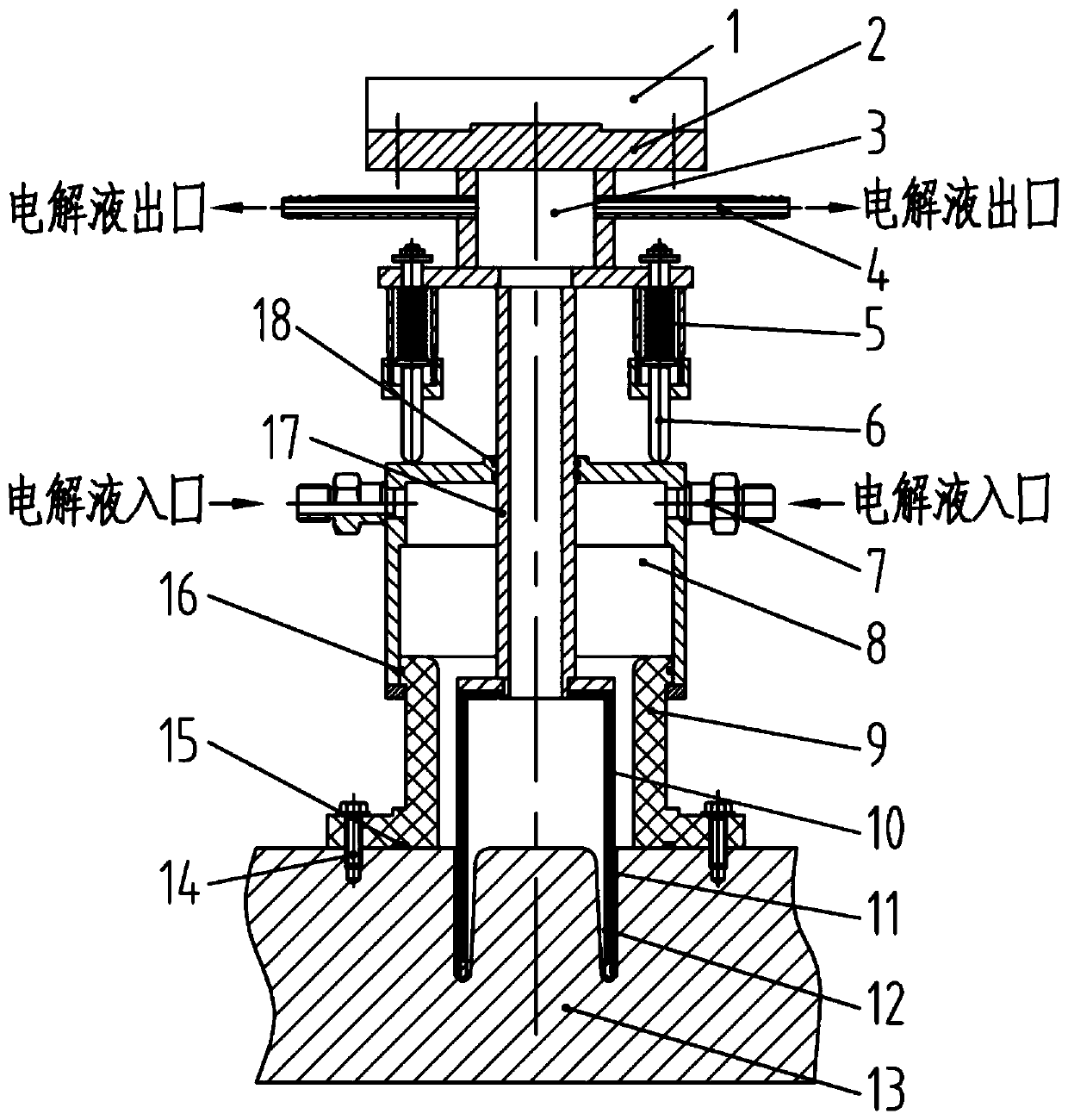
[0030] See attached figure 1 As shown, an electrolyti...


PUM


Abstract

The invention relates to an electrolytic machining device and method for a deep special-shaped hole. The electrolytic machining device comprises a cylindrical structure, a pipe shaft, a fixed liquid accumulation sleeve and a movable liquid accumulation sleeve, wherein the section of the cylindrical structure is provided with a machining cathode of the structure corresponding to and the same as thecontour of the deep special-shaped hole; a through hole for electrolyte to flow through is formed in the pipe shaft, and the machining cathode extends in the length direction of the pipe shaft and isconnected with one end of the pipe shaft; the outer side of the peripheral wall of the pipe shaft is sleeved with the fixed liquid accumulation sleeve, and a gap is formed between the fixed liquid accumulation sleeve and the pipe shaft; and the peripheral wall of the fixed liquid accumulation sleeve is sleeved with one end of the movable liquid accumulation sleeve in a sliding manner, and the peripheral wall of the pipe shaft is sleeved with the other end of the movable liquid accumulation sleeve in a sliding manner. The electrolytic machining device is high in machining efficiency, high in machined product quality and suitable for the deep special-shaped hole and a deep concave cavity which are high in machining difficulty.

Description

technical field [0001] The invention relates to the technical field of electrolytic machining, in particular to an electrolytic machining device and a machining method for deep shaped holes. Background technique [0002] In the structural design of advanced intelligent equipment, in order to improve the strength of the main load-bearing parts and reduce the weight, the overall structure is widely used. Generally, such large-scale overall complex structures are mostly made of titanium alloy materials, with a large number of deep special-shaped holes and deep concave shapes. Cavity, such as cross-sectional size 50mm-120mm, depth 100mm-250mm, if these deep special-shaped holes and deep concave cavities are machined, there will be a large amount of removal, poor accessibility, low efficiency, and high cost, which has become a bottleneck in production question. [0003] Electrolytic machining is a special process method that uses the principle of electrochemical anodic dissoluti...

Claims


Application Information

Patent Timeline
IPC IPC(8): B23H9/14B23H3/10B23H11/00
CPCB23H3/10B23H9/14B23H11/00
Inventor 张明岐张志金
Owner AVIC BEIJING AERONAUTICAL MFG TECH RES INST
Why Eureka
Try Eureka