
Seepage-preventing blocking structure and method for screw hole of concrete shear wall

A technology of concrete shear wall and screw hole, which is applied in the direction of building construction, building maintenance, construction, etc., to achieve the effect of easy operation, fast construction speed and simple structure

Pending Publication Date: 2020-03-06
SHANGHAI NO 7 CONSTR
View PDF0 Cites 9 Cited by
  • Summary
  • Abstract
  • Description
  • Claims
  • Application Information

AI Technical Summary

Problems solved by technology

[0003] The invention provides an anti-seepage sealing structure and method for screw holes in concrete shear walls, which can solve the problem of water seepage at the screw holes at the existing pull bolts, so as to prevent leakage of screw holes and improve project quality the goal of

Method used


Image

  • Seepage-preventing blocking structure and method for screw hole of concrete shear wall
  • Seepage-preventing blocking structure and method for screw hole of concrete shear wall

Examples


Embodiment 1

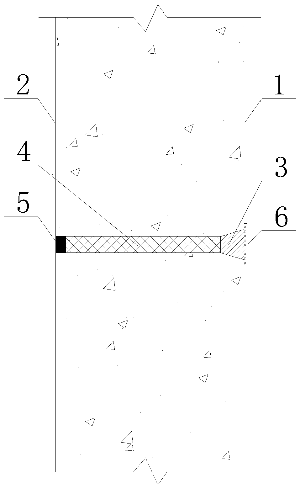
[0030] During the construction, the three-stage water-stop anti-tension screw is used to fix the formwork when the shear wall is poured. The anti-water structure is set on the anti-tension screw. The separate screws on both sides of the wall can be removed and reused. After the formwork is removed, it is removed. Pull screw at the end. This embodiment is aimed at the situation where a screw hole is formed between the concrete shear wall and the pull bolt, the screw hole includes the gap between the screw and the concrete shear wall or even a through hole is formed, in the concrete shear wall The outside 1 of the wall of the shear wall is provided with expansion holes around the pull screw, and the outside 1 of the wall of the shear wall refers to the water-facing surface of the wall. It should be noted that, in order to more clearly show the various components of the anti-seepage sealing structure, figure 2 The pull screw in the wall is not shown in the figure.

[0031] Suc...

Embodiment 2

[0036] This embodiment discloses an anti-seepage sealing method for screw holes in concrete shear walls. figure 2 The anti-seepage plugging method will be further explained. This anti-seepage plugging method comprises the steps:

[0037] Step 1. Check whether there is a screw hole that needs to be sealed between the pull bolt and the concrete shear wall. When there is a plastic pad at the end of the pull screw, remove the plastic pad to form an expansion on the concrete outer wall. hole; when the end of the pull screw is not provided with a plastic spacer, use a percussion drill to expand the hole on the outside of the wall 1 centered on the pull bolt to form an expanded hole, remove the PVC pipe in the expanded hole, and remove the PVC pipe in the hole. Clean up the debris;

[0038] In order to achieve a better anti-seepage effect, the depth of the expanded hole is not less than 20mm, and the diameter is not less than 30mm;

[0039] Step 2. Use a wire brush to clean up th...


PUM

PropertyMeasurementUnit
Diameteraaaaaaaaaa
Depthaaaaaaaaaa
Diameteraaaaaaaaaa

Abstract

The invention discloses a seepage-preventing blocking structure and method for a screw hole of a concrete shear wall, and belongs to the technical field of seepage prevention of concrete shear walls.The seepage-preventing blocking structure comprises a polyurethane foaming agent arranged in the screw hole, asbestos cement arranged in an expansion hole, a waterproof material which is applied to the outer side of a wall body of the concrete shear wall through brushing and covers the asbestos cement as well as dry and hard cement mortar arranged in the screw hole in the inner side of the wall body of the concrete shear wall in a filling manner. According to the seepage-preventing blocking structure and method, the expansion hole is formed, the asbestos cement is arranged in the expansion hole for blockage, the polyurethane foaming agent is injected into the screw hole, the outer side of the shear wall is brushed with the waterproof material, and a compact structure is formed at the screwhole of a pull screw, so that the purposes of completely eradicating seepage of the screw hole and improving the project quality are achieved.

Description

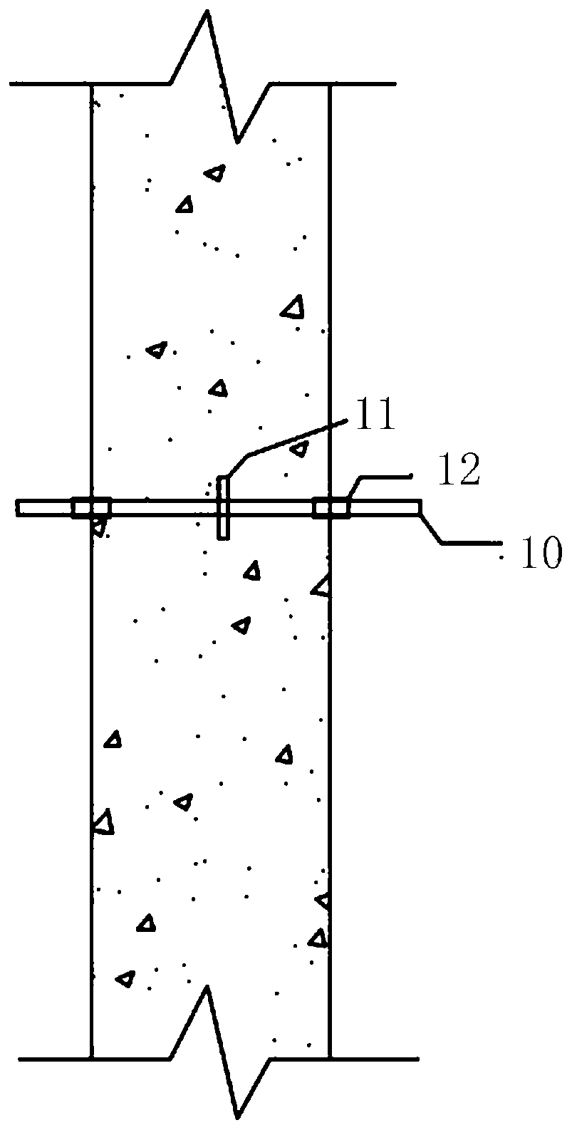
technical field [0001] The invention relates to an anti-seepage sealing structure and method for a screw hole in a concrete shear wall, and belongs to the technical field of anti-seepage of a concrete shear wall. Background technique [0002] During the construction of concrete shear walls, for parts with high waterproof requirements (especially in the construction of underground structures), the shear wall formwork often uses three-stage water-stop tensioning screws to fix the formwork on both sides of the wall to ensure that the bolts Water repellent effect on the sides. Such as figure 1 As shown, a waterproof steel plate 11 is arranged on the pull screw 10 in the shear wall, and threaded sleeves 12 are arranged at both ends of the pull screw. However, it is easy to loosen the anti-tension screw during construction, so that a gap is formed between the anti-tension screw and the concrete of the shear wall. Body screw hole. Under the influence of various unfavorable cond...

Claims


Application Information

Patent Timeline
IPC IPC(8): E04G23/02
CPCE04G23/0203E04G23/0211
Inventor 陈甦秦立标邵俊华郑杰胡稳吴炜程
Owner SHANGHAI NO 7 CONSTR
Learn More