Knife rest structure of simple automatic lathe

A technology of automatic lathes and tool holders, which is applied in the direction of large fixed members, metal processing machinery parts, metal processing equipment, etc., can solve the problems of insufficient precision, low improvement cost, instability, etc., to improve processing accuracy, reduce labor costs, smooth control effect

Pending Publication Date: 2020-03-10
东莞市中煌五金制品有限公司
View PDF0 Cites 0 Cited by
  • Summary
  • Abstract
  • Description
  • Claims
  • Application Information

AI Technical Summary

Problems solved by technology

[0004] One of the tool holders of the simple automatic lathe is controlled by the cam through the arm structure. The displacement and formation are mainly controlled by the cam. When changing the machine to make a new product, a cam is required. The cam controls the product size to fluctuate and become unstable; There are many steps in the outer diameter of the product, it is difficult to control the size, the arc slope cannot be done, the precision is not enough, and it takes too long for the technician to adjust the machine, which is a waste of time
[0005] Although there are precision automatic lathes with five sets of tool holders on the market, as well as full CNC precision machining lathes, they all have the problem of high cost and need to be replaced wholeheartedly. At present, most small and medium-sized enterprises are using Simple automatic lathes, and the number is large, if you want to replace all of them with CNC lathes or precision automatic lathes with five sets of tool holders, the cost and benefit are not directly proportional; how to improve the structure of more simple automatic lathes so that Higher processing progress and lower improvement cost have become problems faced by most small and medium-sized enterprises in this field

Method used


Image

  • Knife rest structure of simple automatic lathe
  • Knife rest structure of simple automatic lathe
  • Knife rest structure of simple automatic lathe

Examples


Embodiment 1

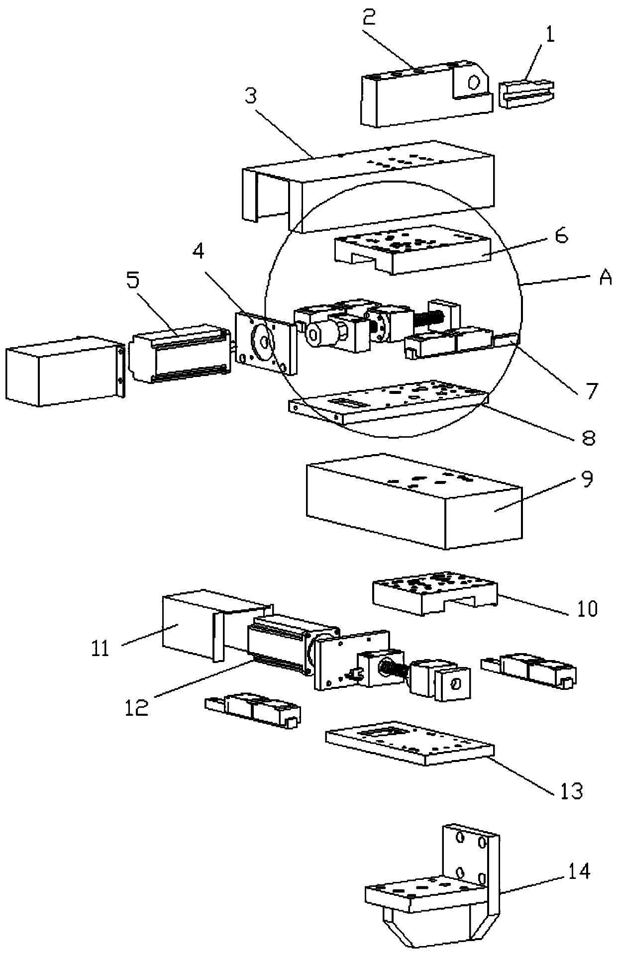
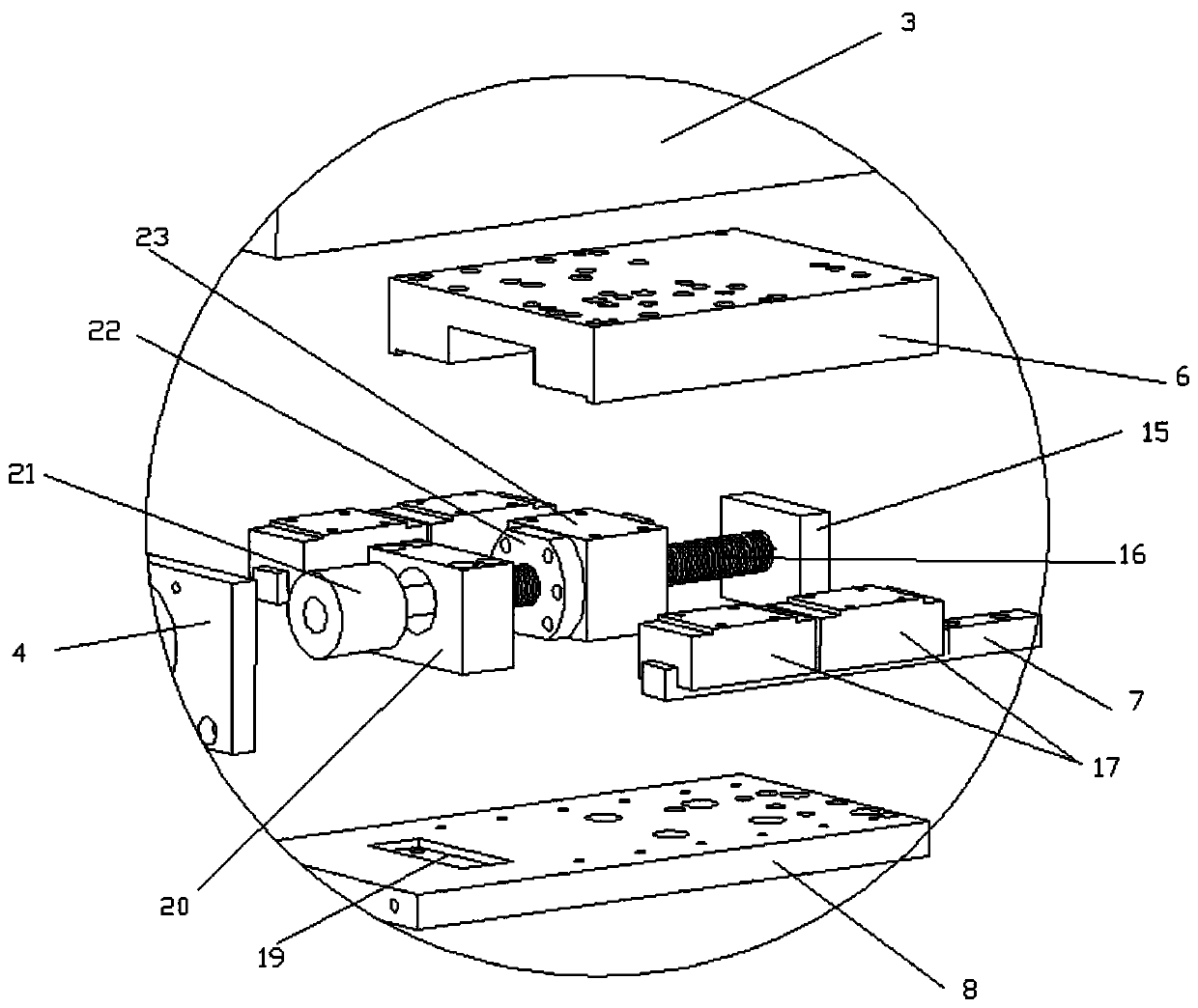
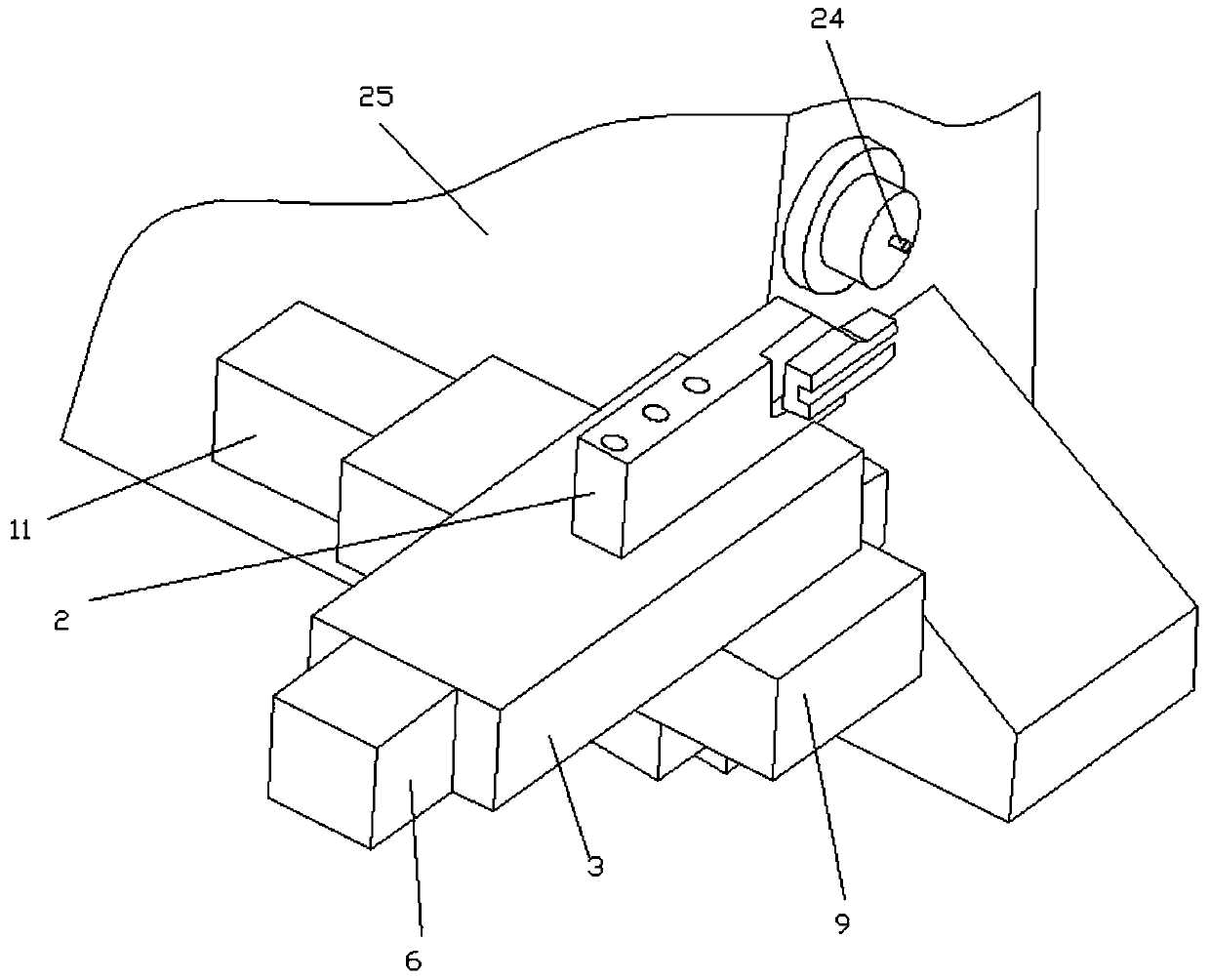
[0023] Such as Figure 1-3 As shown, the tool holder structure of a simple automatic lathe of the present invention includes an axial screw pushing mechanism, a radial screw pushing mechanism, a turning knife fixing mechanism and a fixed base 14; the axial screw pushing mechanism is fixed by the fixed base 14 On the side of the lathe, the radial screw pushing mechanism is connected with the axial screw pushing mechanism and controlled by it to move along the axial direction of the parts processed by the lathe; the turning knife fixing mechanism is connected with the radial screw pushing mechanism and controlled by it to move along the lathe The radial movement of the parts, the turning tool fixing mechanism is used to fix the turning tool.

[0024] The radial screw push mechanism includes a radial control motor 5, a radial motor shield, a radial motor seat plate 4, a radial fixing plate 8, a radial transmission screw 16, a radial slider, a radial slide table 6, a radial Slide...


PUM


Abstract

The invention relates to a knife rest structure of a simple automatic lathe, and belongs to the field of cam type automatic lathes. The knife rest structure comprises an axial screw pushing mechanism,a radial screw pushing mechanism, a turning cutter fixing mechanism and a fixed base, wherein the axial screw pushing mechanism is fixed to the side surface of the lathe by virtue of the fixed base,and the radial screw pushing mechanism is connected with the axial screw pushing mechanism and is controlled to axially move along a to-be-processed part of the lathe by the axial screw pushing mechanism; the turning cutter fixing mechanism is connected with the radial screw pushing mechanism and is controlled to radially move along the to-be-processed part of the lathe by the radial screw pushingmechanism, and the turning cutter fixing mechanism is used for fixing a turning cutter. On the basis of an existing simple automatic lathe, the knife rest structure is improved, so that the numericalcontrol over one knife rest of the simple automatic lathe is realized, and the turning cutter is controlled to move by virtue of two groups of screws, so that the machining precision is effectively increased, and rebuilding at low cost is realized.

Description

technical field [0001] The invention relates to a tool holder structure of a simple automatic lathe, which belongs to the field of cam type automatic lathes. Background technique [0002] Cam-type automatic lathe is an automatic processing machine tool that controls the processing program through a cam. It is widely used in mechanical processing automatic machine tools. It is characterized by fast processing speed, high processing accuracy, automatic feeding, and automatic stop when the material is finished. One person can Operate multiple machine tools. Cam-type automatic lathes are divided into simple automatic lathes and precision automatic lathes. [0003] The simple automatic lathe has a main shaft, two sets of tool holders, and is driven by one or two sets of simple cams. It can feed material from the front or back. The processing procedure is simple and the processing accuracy is relatively low. automatic lathe. [0004] One of the tool holders of the simple automa...

Claims


Application Information

Patent Timeline
Patent Type & Authority Applications(China)
IPC IPC(8): B23B21/00
CPCB23Q1/25
Inventor 房玉超曾炜
Owner 东莞市中煌五金制品有限公司
Why Eureka
Try Eureka