
Cyclic chained die for plastic particle forming

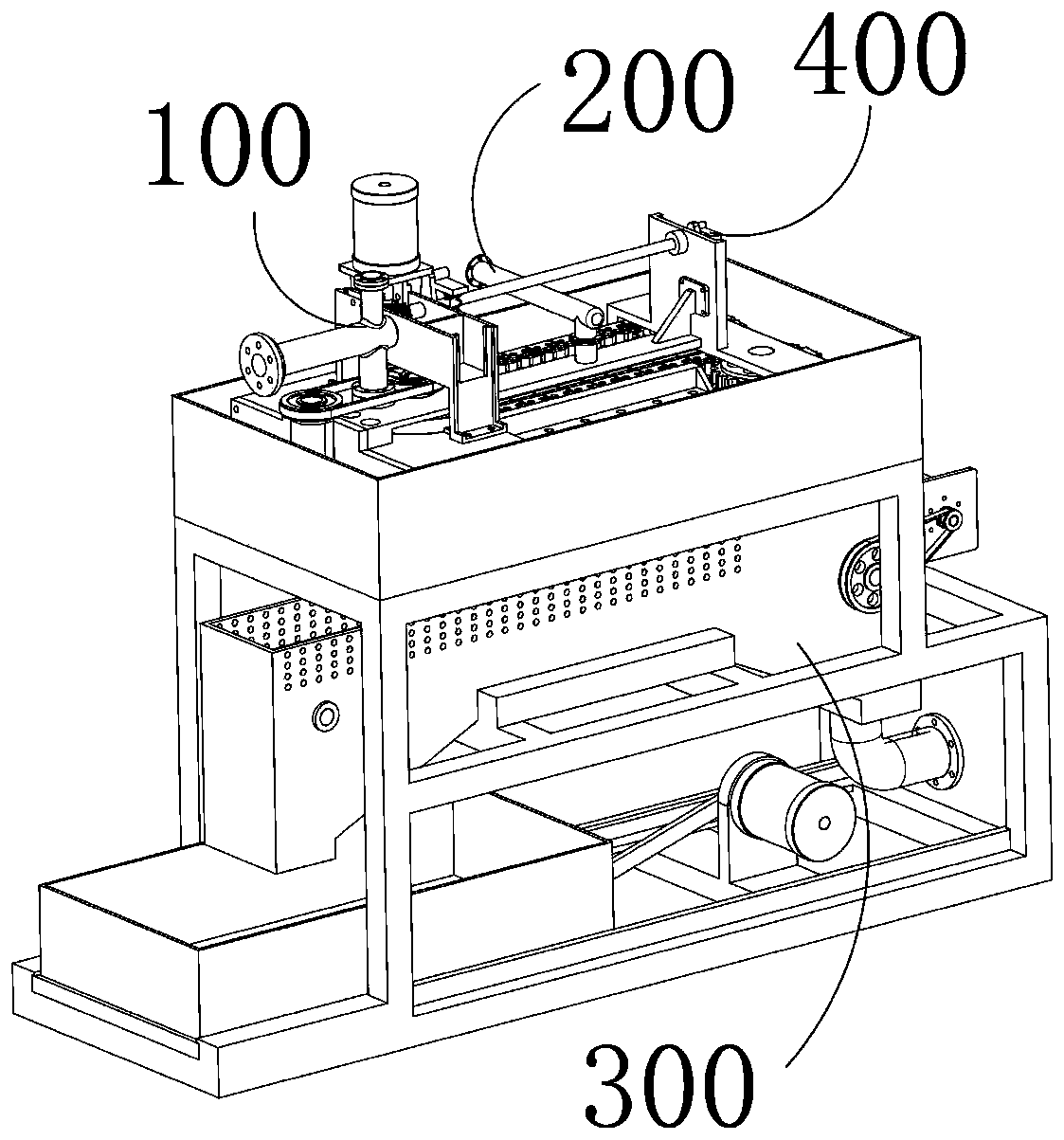
A technology of plastic granules and molds, which is applied in the field of plastic processing, can solve the problems of non-uniform specifications, unstable shape of plastic granules, unfavorable sales and fine processing, etc.

Inactive Publication Date: 2020-03-10
六安丰恺尼机电科技有限公司
View PDF6 Cites 0 Cited by
  • Summary
  • Abstract
  • Description
  • Claims
  • Application Information

AI Technical Summary

Problems solved by technology

[0002] At present, the recycling technology of waste plastics is becoming more and more mature. The existing plastic granulators generally extrude strips of plastics through extrusion molding mechanisms, and then cut the strips of plastics to obtain plastic granules. However, through this Most of the plastic particles obtained by this method are not fixed in shape and specifications, which is not conducive to subsequent sales and finishing treatment. Injection molding, also known as injection molding, is a molding method of injection and molding. The advantages are fast production speed, high efficiency, automatic operation, simple to complex shapes, large to small sizes, accurate product sizes, easy replacement of products, and the ability to form complex shaped parts. Injection molding is suitable for a large number of It is one of the important industrial processing methods in the field of molding and processing of products with complex shapes. This invention proposes a plastic granulation equipment that adopts chain mold injection molding. Its injection molding is transported to the chain mold for cooling and molding, and the obtained plastic particles are of the same size and good quality, which is convenient for subsequent sales

Method used


Image

  • Cyclic chained die for plastic particle forming
  • Cyclic chained die for plastic particle forming
  • Cyclic chained die for plastic particle forming

Examples


Embodiment Construction

[0084]The present invention has the advantage of receiving molten plastic and granulating it in that it can obtain plastic granules that meet the production requirements. During the melting and molding conveying process, the heating element arranged outside the mold body will keep the plastic molten in the mold body. state; during the cooling molding process, the cooling water is in contact with the molten plastic in the form of spraying, which can increase the contact area between the two, and the cooling water is also cooled by flowing water, and the cooling effect is better; during the output of plastic particles, Air-dry the moisture on the surface of the plastic granules through the fan, which reduces the heat consumption required for the melting of the plastic granules in the subsequent utilization process, and also facilitates the long-term storage of the plastic granules; in addition, after the granules are shaped in the mold body In the process of dropping molten plast...


PUM


Abstract

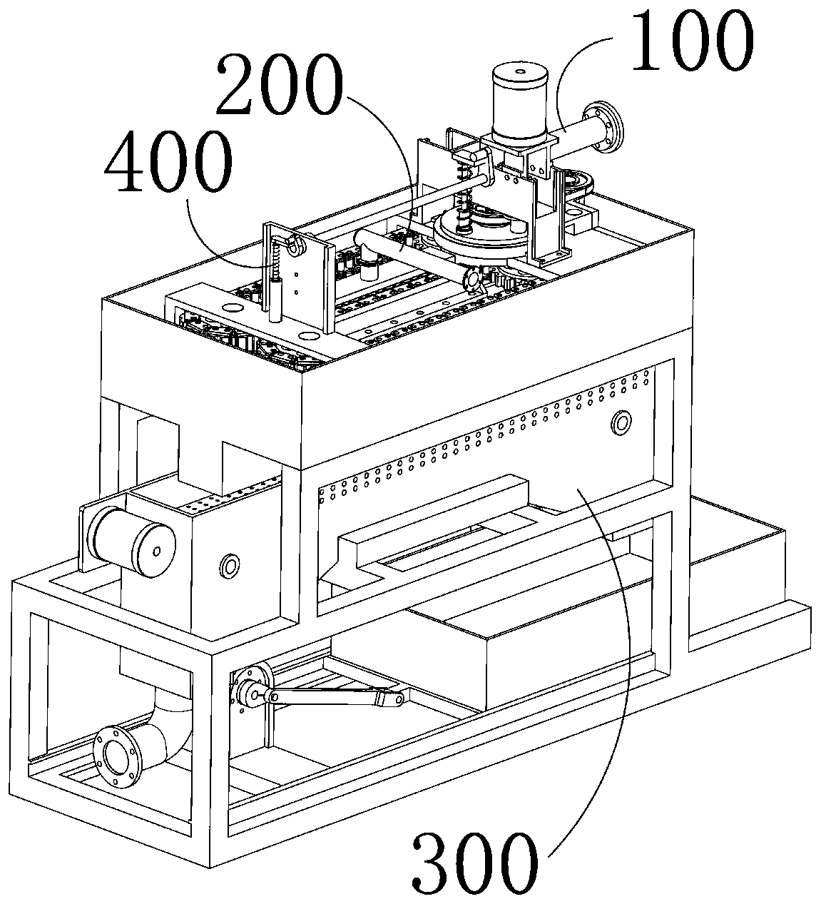
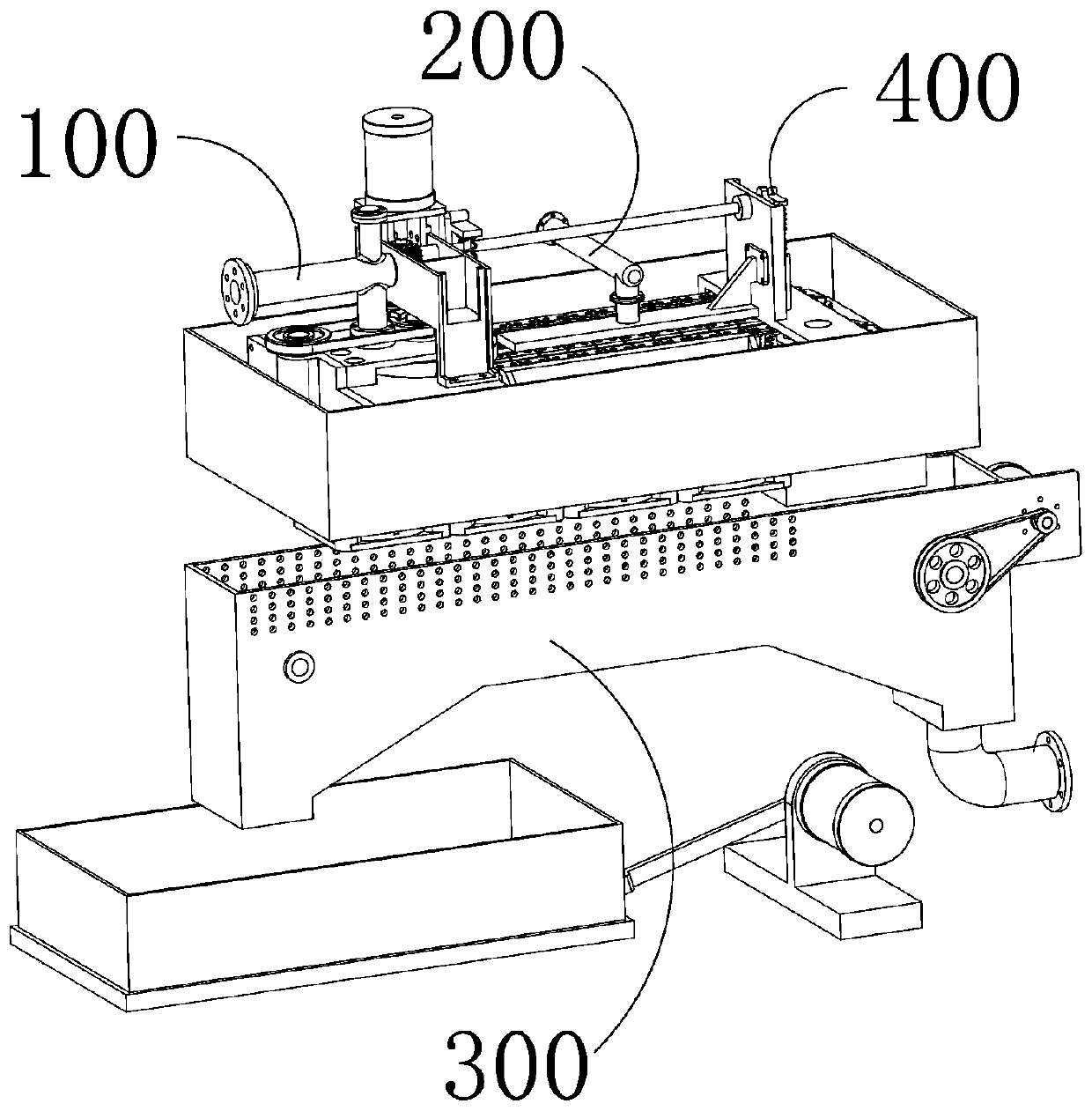
The invention provides a cyclic chained die for plastic particle forming. The cyclic chained die comprises a main frame body, a die device, a water cooling forming device and a water separating and output device. The main frame body is fixedly provided with a cooling water tank with an opened upper end and a closed lower end. The die device and the water cooling forming device are installed in thecooling water tank. The water separating and output device is located under the cooling water tank. The die device is used for receiving molten plastic and forming the molten plastic into a proper particle shape. The water cooling forming device is used for receiving the particle-shaped molten plastic output by the die device and conducting water cooling and condensation forming treatment on themolten plastic. The water separating and output device is used for receiving a cooling water and plastic particle mixture output by the water cooling forming device and conducting separating and output treatment on the mixture. By means of the cyclic chained die, after the molten plastic is subjected to particle shaping treatment, the molten plastic is conveyed into the chained die to be subjectedto cooling forming, obtained plastic particles are consistent in size, the quality is good, and subsequent selling is facilitated.

Description

technical field [0001] The invention relates to the field of plastic processing, in particular to a plastic granulator. Background technique [0002] At present, the recycling technology of waste plastics is becoming more and more mature. The existing plastic granulators generally extrude strips of plastics through extrusion molding mechanisms, and then cut the strips of plastics to obtain plastic granules. However, through this Most of the plastic particles obtained by this method are not fixed in shape and specifications, which is not conducive to subsequent sales and finishing treatment. Injection molding, also known as injection molding, is a molding method of injection and molding. The advantages are fast production speed, high efficiency, automatic operation, simple to complex shapes, large to small sizes, accurate product sizes, easy replacement of products, and the ability to form complex shaped parts. Injection molding is suitable for a large number of It is one of...

Claims


Application Information

Patent Timeline
IPC IPC(8): B29B9/10B29C45/73B29B17/00B29C45/17B29C45/26B29C45/46
CPCB29B9/10B29B17/00B29C45/17B29C45/1756B29C45/26B29C45/46B29C45/73Y02W30/62
Inventor 陆永柱祝磊丁先虎
Owner 六安丰恺尼机电科技有限公司
Learn More