

Oil net structure and range hood
An oil net and air net technology, applied in the field of oil net structure and range hood, can solve the problems of poor condensation effect, unfavorable and rapid removal of oil fume, slow air inlet speed, etc., so as to improve the condensation effect, improve the oil fume separation effect, improve The effect of flow
- Summary
- Abstract
- Description
- Claims
- Application Information
AI Technical Summary
Problems solved by technology
Method used
Image

Examples
Embodiment
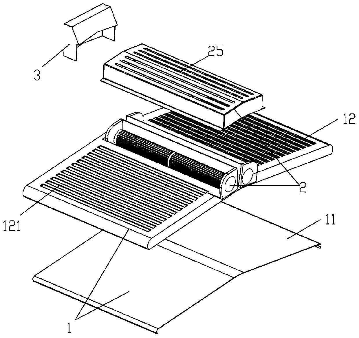
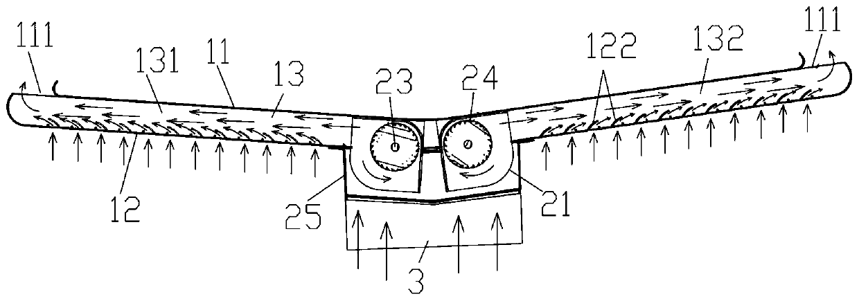
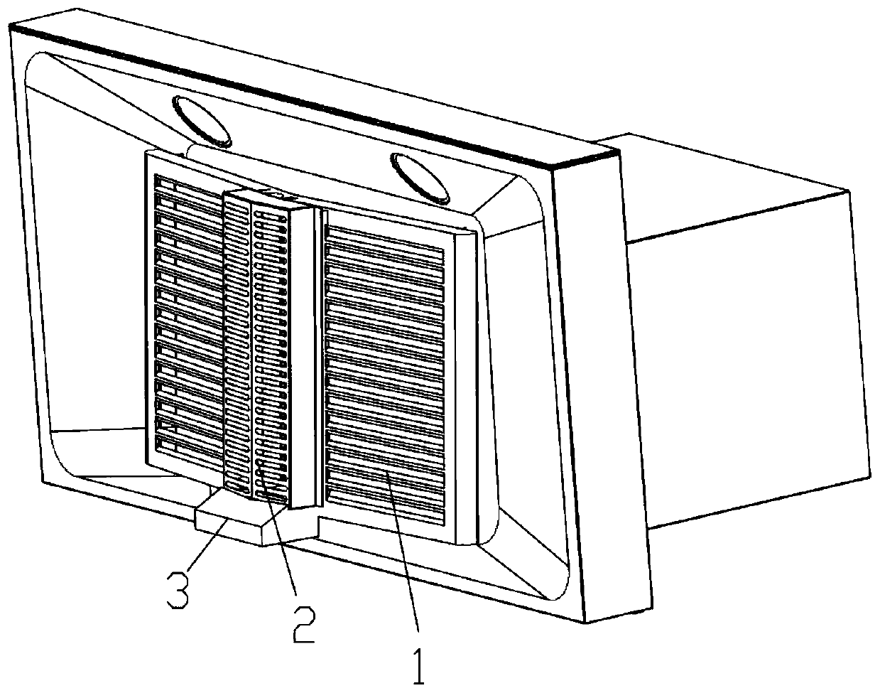
[0021] See attached Figure 1-3 , a kind of oil screen structure, including the upper condensing plate 11 and the lower air net 12 that form the air net group 1, the lower air net 12 is provided with an air inlet end 121, and the left and right sides of the upper condensing plate 11 are provided with air outlet end 111, there is a gap between the upper condensing plate 11 and the lower air net 12 to form a flow channel 13 from the air inlet end to the air outlet end, and the air blower 2 is also arranged on the air net group 1, so The air outlet of the blower device 2 is located on the flow channel 13 and blows air to the air outlet end 111 to increase the wind speed and negative pressure of the flow channel 13. By forming the structure of the lower air net 12 and the upper condensation plate 11, the lower air net 12 It can block the heat radiation while entering the wind, so that the temperature of the upper condensing plate 11 is not high, and the condensation effect is impr...
PUM
 Abstract
Description
Claims
Application Information