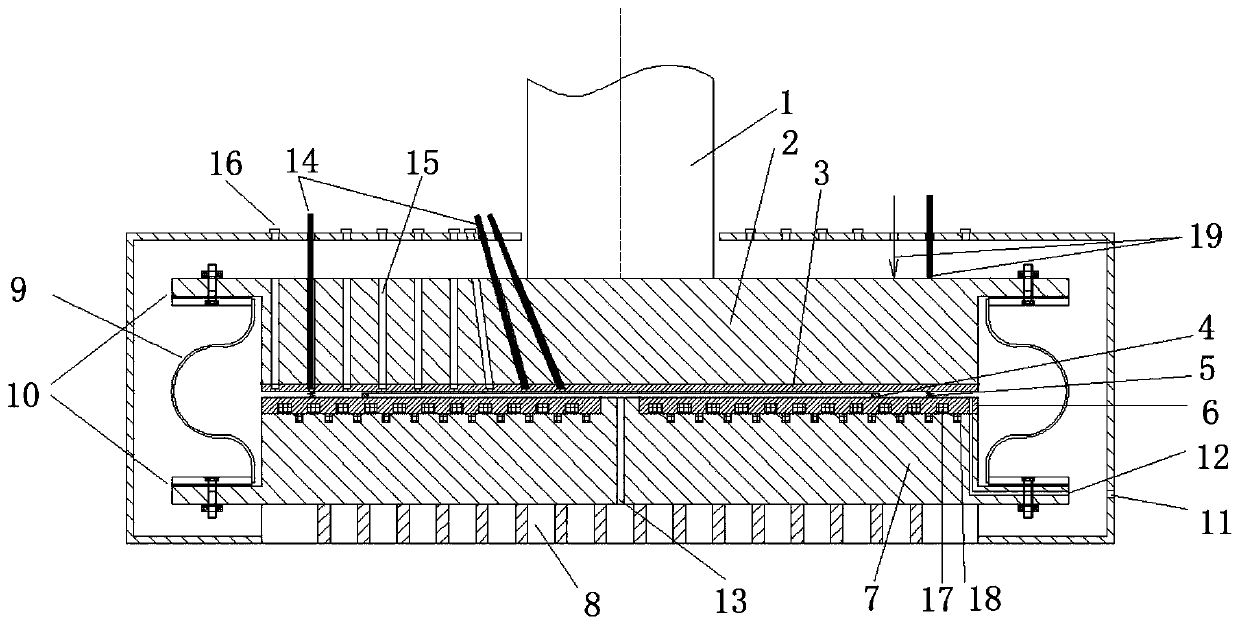
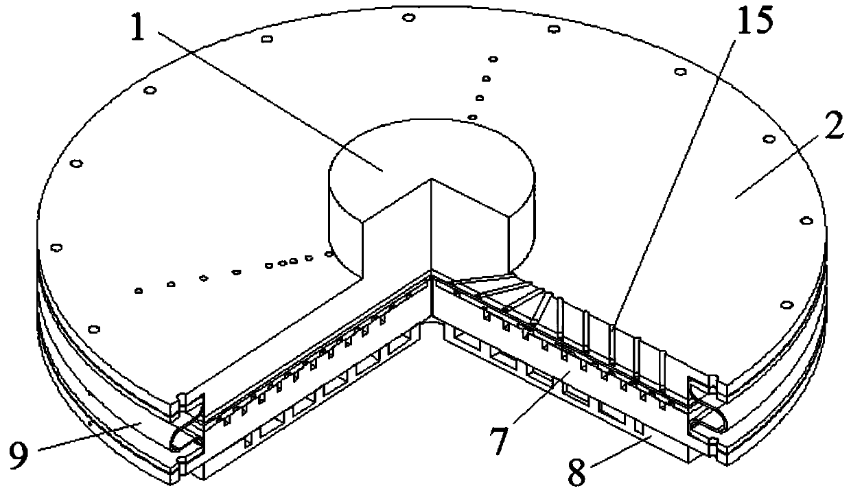
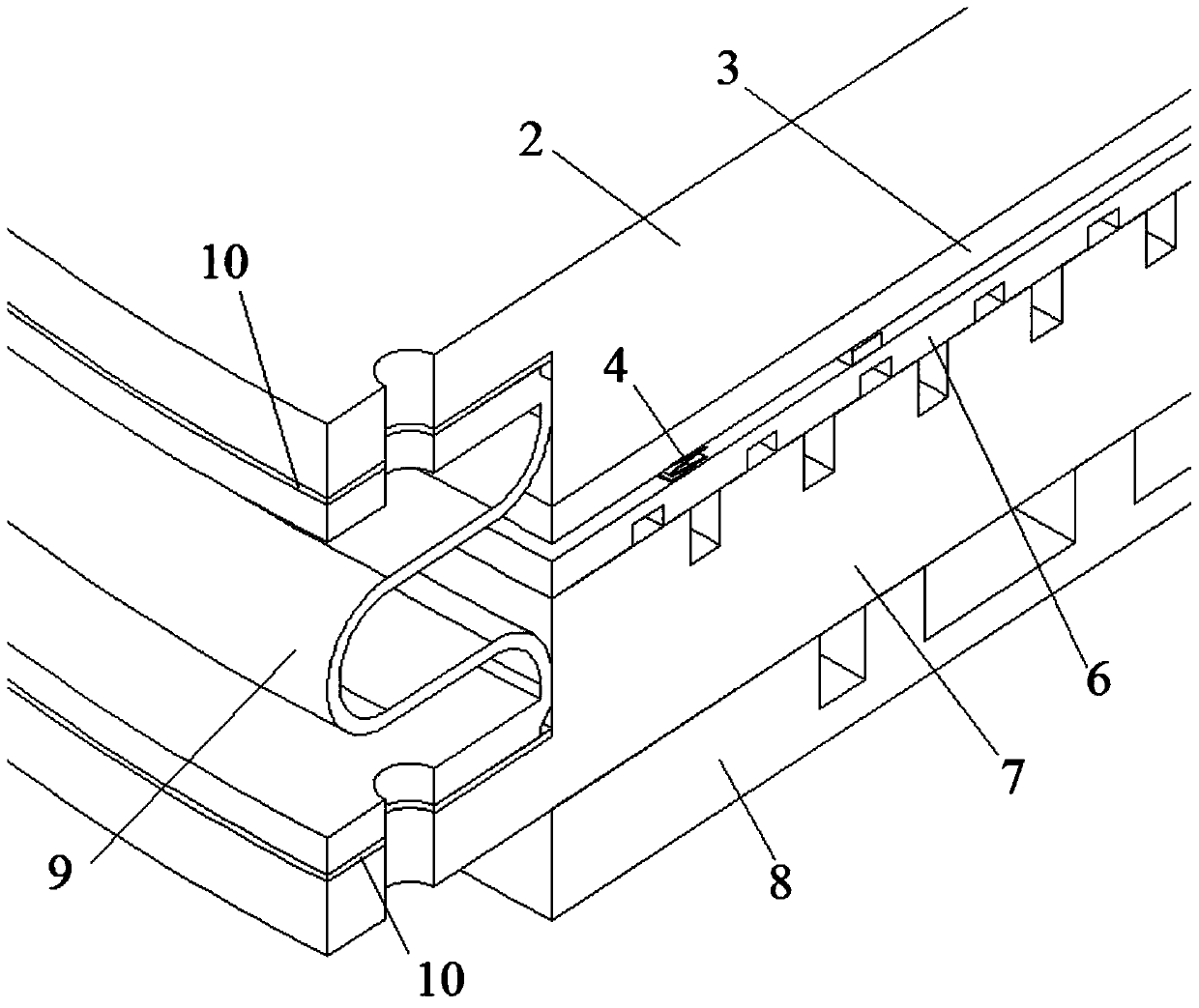
Sealing ring test device with deformation error compensation function
A test device, deformation error technology, applied in the direction of measuring device, testing of mechanical parts, testing of machine/structural parts, etc., can solve the large dynamic friction between the connecting rod of the pressure plate and the high-pressure container, cannot accurately measure the loading force, increase the test It can avoid problems such as heating power of the machine, and achieve the effect of avoiding difficult sealing, good sealing and high reliability.
- Summary
- Abstract
- Description
- Claims
- Application Information
AI Technical Summary
Problems solved by technology
Method used
Image

Examples
Embodiment Construction
[0026] The following will clearly and completely describe the technical solutions in the embodiments of the present invention with reference to the accompanying drawings in the embodiments of the present invention. Obviously, the described embodiments are only some, not all, embodiments of the present invention. Based on the embodiments of the present invention, all other embodiments obtained by persons of ordinary skill in the art without making creative efforts belong to the protection scope of the present invention.
[0027] The purpose of the present invention is to provide a sealing ring test device with deformation error compensation to solve the problems in the prior art, reduce the thermal energy, mechanical energy and high-pressure gas energy required for the test, and improve the loading force and deformation of the test piece Excellent measurement accuracy, improve the controllability of pressure ring force.
[0028] In order to make the above objects, features and ...
PUM
 Abstract
Description
Claims
Application Information
 - Generate Ideas
- Intellectual Property
- Life Sciences
- Materials
- Tech Scout
- Unparalleled Data Quality
- Higher Quality Content
- 60% Fewer Hallucinations
Browse by: Latest US Patents, China's latest patents, Technical Efficacy Thesaurus, Application Domain, Technology Topic, Popular Technical Reports.
© 2025 PatSnap. All rights reserved.Legal|Privacy policy|Modern Slavery Act Transparency Statement|Sitemap|About US| Contact US: help@patsnap.com