Heat dissipation device of CT scanning machine, CT scanning frame and CT scanning machine

A heat dissipation device and scanner technology, which is applied in the field of medical equipment, can solve problems such as high operating noise and thick appearance of CT scanning frames, and achieve the effect of reducing volume, realizing lightweight design, and good heat dissipation

Pending Publication Date: 2020-03-17
SAINUO WEISHENG SCI & TECH BEIJING
View PDF0 Cites 1 Cited by
  • Summary
  • Abstract
  • Description
  • Claims
  • Application Information

AI Technical Summary

Problems solved by technology

[0004] The main purpose of the application of the present invention is to provide a heat dissipation device for a CT scanning machine, a CT scanning frame and a CT scanning machine, which solves the problem of CT due to the fact that a conventional CT scanning frame needs to use a fan with a large flow rate and a large appearance for system cooling. The appearance of the scanning frame is heavy and the technical problems of the loud running noise

Method used


Image

  • Heat dissipation device of CT scanning machine, CT scanning frame and CT scanning machine
  • Heat dissipation device of CT scanning machine, CT scanning frame and CT scanning machine
  • Heat dissipation device of CT scanning machine, CT scanning frame and CT scanning machine

Examples


Embodiment Construction

[0028] In order to enable those skilled in the art to better understand the application solution of the present invention, the technical solution in the application embodiment of the present invention will be clearly and completely described below in conjunction with the accompanying drawings in the application embodiment of the present invention. Obviously, the described The embodiments are only some embodiments of the application of the present invention, not all embodiments. Based on the embodiments in the application of the present invention, all other embodiments obtained by persons of ordinary skill in the art without creative efforts shall fall within the protection scope of the application of the present invention.

[0029] It should be noted that the terms "first" and "second" in the specification and claims of the present application and the above drawings are used to distinguish similar objects, but not necessarily to describe a specific order or sequence . It shou...


PUM


Abstract

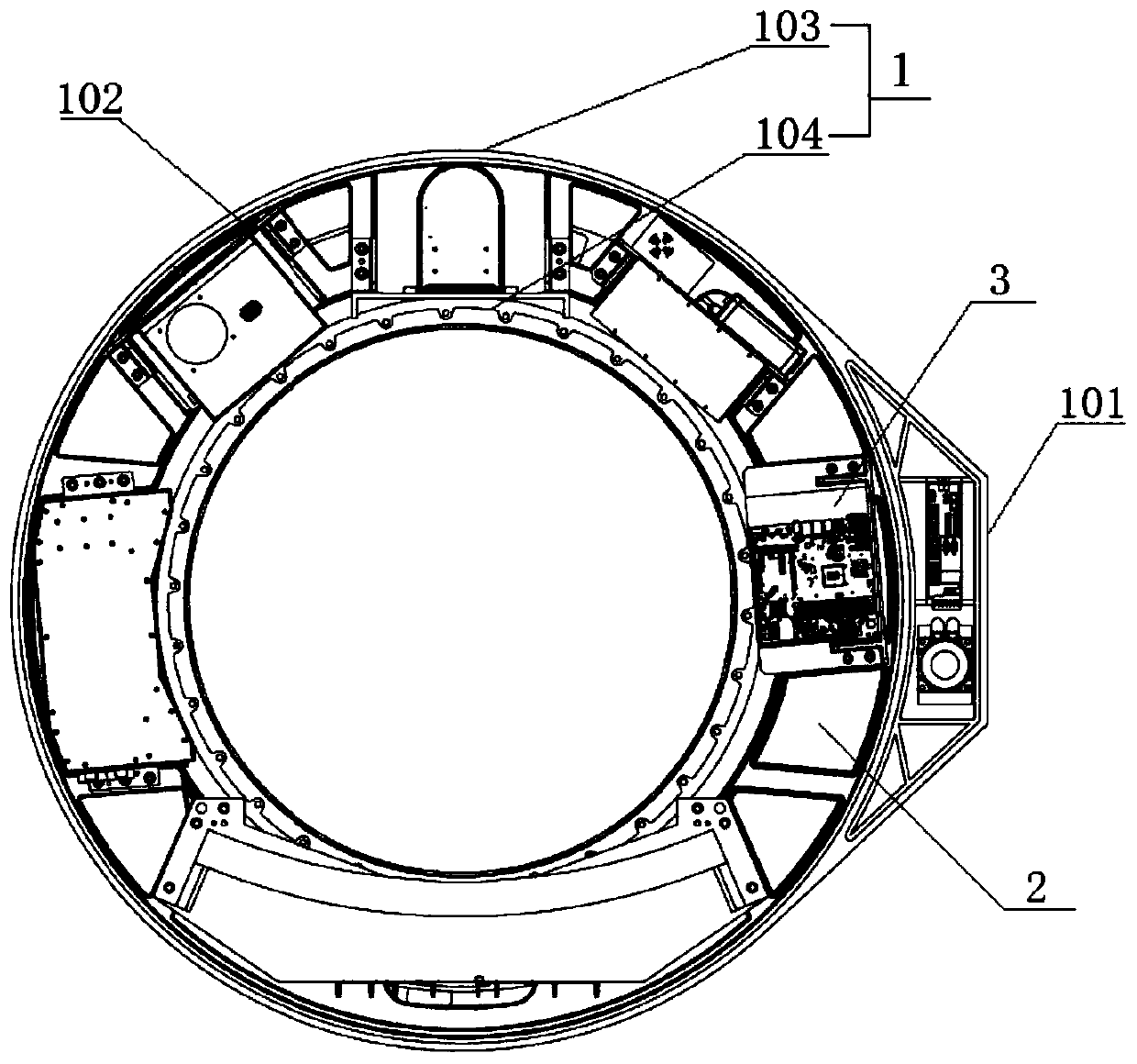
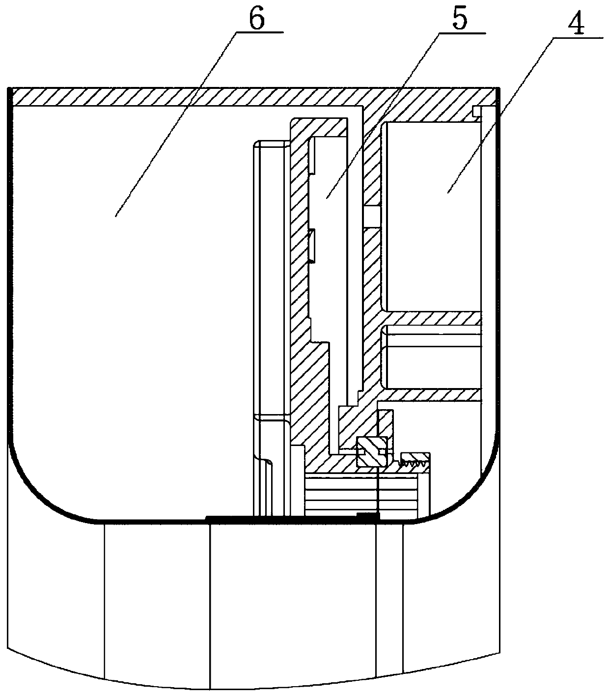
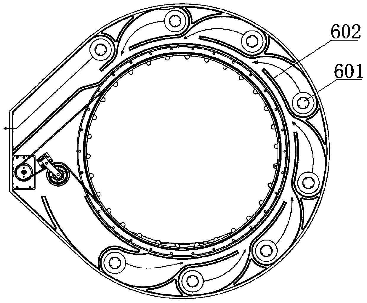
The invention discloses a heat dissipation device. The heat dissipation device comprises a shell (1), an air duct (2) in the shell (1), wherein a heating part and a rotary support for fixing the position of the heating part are arranged in the air duct (2), and an air inlet (101) and an air outlet (102) formed in the air duct (2), wherein the air duct (2) guides air which enters from the air inlet(101), flows through the heating part in the rotary support and is exhausted from the air outlet (102). The technical problems that a conventional CT scanning frame needs a fan with large flow and large size to conduct system heat dissipation so that the CT scanning frame is thick and heavy and operation noise is large are solved.

Description

technical field [0001] The application of the present invention relates to the field of medical equipment, in particular, to a heat dissipation device of a CT scanning machine, a CT scanning frame and a CT scanning machine. Background technique [0002] The traditional CT (Computed Tomography computer tomography) scanning system scanning frame is mainly composed of X-ray source (ball tube), detector, high-voltage generator, rotating drive device, rotating support, fixed support and main rotating bearing, etc., and uses an outer cover The above components are wrapped inside to achieve aesthetics and protect patients and operators. During clinical use, tubes, detectors and other electronic and electrical components will generate a lot of heat in the enclosed space of the outer cover. If the heat cannot be dissipated to the external environment in an effective way, it will seriously affect the detector. The accuracy of the work and the life of the electronic and electrical com...

Claims


Application Information

Patent Timeline
Patent Type & Authority Applications(China)
IPC IPC(8): A61B6/00A61B6/03F25D1/00F04D25/08F04D29/44
CPCA61B6/035A61B6/4435A61B6/4488F04D25/08F04D29/444F25D1/00
Inventor 王君涛任敬轶
Owner SAINUO WEISHENG SCI & TECH BEIJING
Why Eureka
Try Eureka