Steel bar electric welding equipment for laminated slab machining

A technology of electric welding equipment and laminated board, which is applied in metal processing equipment, welding equipment, auxiliary welding equipment, etc., can solve the problems of labor loss, decreased electric welding efficiency, low efficiency, etc., and achieves low manufacturing cost, increased efficiency, and simple setup. Effect

Active Publication Date: 2020-03-17
马鞍山华亿工程技术有限公司
View PDF18 Cites 17 Cited by
  • Summary
  • Abstract
  • Description
  • Claims
  • Application Information

AI Technical Summary

Problems solved by technology

[0004] The object of the present invention is to provide a steel bar electric welding equipment for processing laminated plates, which solves the following technical problems: (1) The output shaft of the first motor drives the gear to rotate, and the gear cooperates with the rack to drive the entry and exit plate to slide on the bottom plate, and then enters and exits The plate is removed from the welding frame, the operator puts the laminated plate on the surface of the bottom plate, and the first motor moves the incoming and outgoing plate back into the welding, which solves the technical problem of low efficiency of the upper and lower plates in the prior art when the laminated plate is welded; (2) The piston rod of the telescopic cylinder drives the connecting plate to adjust to the positions on both sides of the laminated plate. The output shaft of the second motor drives the first screw to rotate, and the first screw drives the second screw to rotate through the connecting rod sleeve. The two first The screw rod and the two second screw rods respectively drive the four connecting seats to move toward each other through the nuts, and then drive the four clamping blocks to move toward each other through the fixed rod. Clamping, after clamping, the telescopic cylinder piston rod drives the clamped laminated plate to rise, and the turning cylinder drives the laminated plate to turn over, solving the problem that the steel bars on the laminated plate in the prior art often need the operator to turn over the plate when performing double-sided electric welding On the one hand, it causes labor loss and reduces the efficiency of the entire electric welding

Method used


Image

  • Steel bar electric welding equipment for laminated slab machining
  • Steel bar electric welding equipment for laminated slab machining
  • Steel bar electric welding equipment for laminated slab machining

Examples


Embodiment Construction

[0029] The following will clearly and completely describe the technical solutions in the embodiments of the present invention with reference to the accompanying drawings in the embodiments of the present invention. Obviously, the described embodiments are only some, not all, embodiments of the present invention. Based on the embodiments of the present invention, all other embodiments obtained by persons of ordinary skill in the art without creative efforts fall within the protection scope of the present invention.

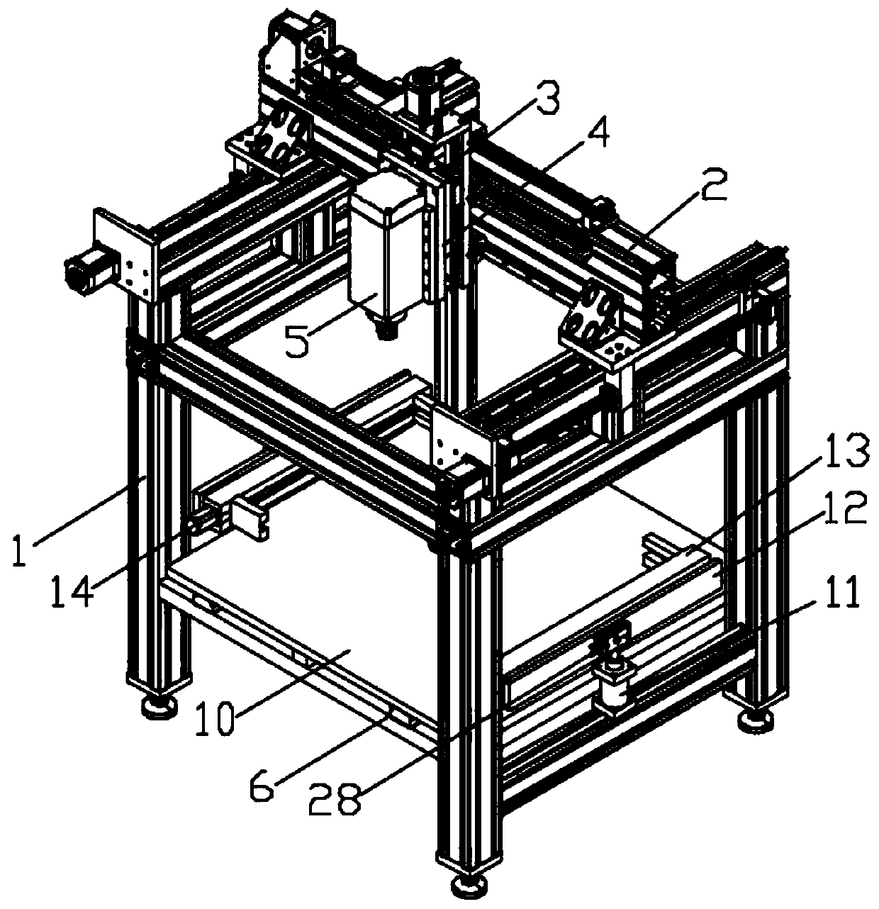
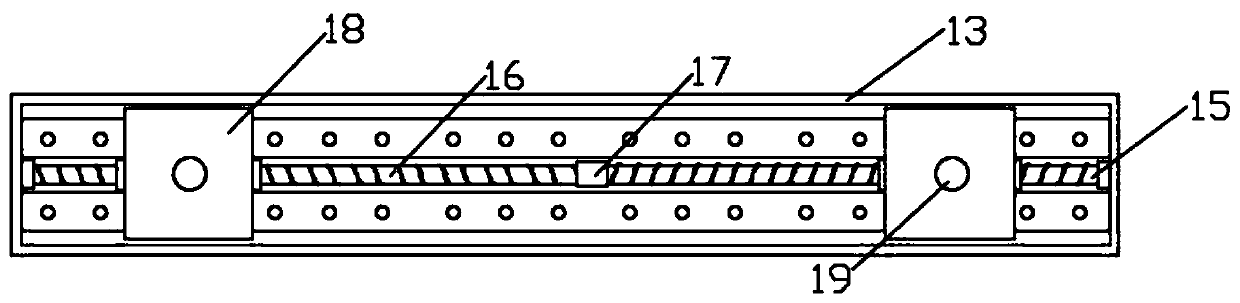
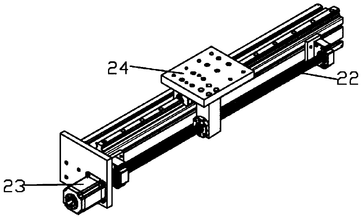
[0030] see Figure 1-7 As shown, the present invention is a steel bar electric welding equipment for processing laminated plates, including a welding frame 1, a moving beam 2 is slidably installed on the top of the welding frame 1, and a translation plate 3 is slidably installed on one side of the moving beam 2, and on the translation plate 3 The lifting plate 4 is slidably installed, the welding head 5 is installed on the lifting plate 4, the base plate 6 is also ...


PUM


Abstract

The invention discloses steel bar electric welding equipment for laminated slab machining. The welding equipment comprises a welding frame, a moving beam is slidably mounted at the top of the weldingframe, a translation plate is slidably mounted on one side of the moving beam, a lifting plate is slidably mounted on the translation plate, a welding head is mounted on the lifting plate, a bottom plate is further mounted on the welding frame and mounted at the position, close to the bottom, of the welding frame, and a first motor is mounted on the lower surface of the bottom plate. The four corners of the two sides of the laminated plate are clamped through the grooves in the clamping blocks; after clamping, a piston rod of a telescopic air cylinder drives the clamped laminated plate to ascend, a turnover air cylinder drives the laminated plate to turn over, and the problems that in the prior art, when steel bars on the laminated plate are subjected to double-face electric welding, an operator often needs to turn over the plate face, so labor loss is caused, and meanwhile the whole electric welding efficiency is reduced are solved.

Description

technical field [0001] The invention relates to the technical field of laminated plate processing, in particular to a steel bar electric welding equipment used for laminated plate processing. Background technique [0002] The laminated slab is an assembled integral floor slab formed by laminating prefabricated slabs and cast-in-place reinforced concrete layers. Existing electric welding of steel bars in laminated slabs is usually double-sided spot welding and single-sided spot welding. Double-sided electric welding is the method of choice for more laminated slab steel bars because of its good shape and high weld quality. [0003] In the prior art, the operator needs to put the laminated plate into the welding frame before welding. Due to the space limitation of the welding frame, it is not very convenient to put the upper plate and the lower plate of the laminated plate. After one side of the plywood is welded, the plywood is turned over by itself, and then the steel bar on...

Claims


Application Information

Patent Timeline
Patent Type & Authority Applications(China)
IPC IPC(8): B23K37/02B23K37/04B23K37/047
CPCB23K37/0229B23K37/0247B23K37/0408B23K37/0461B23K37/047
Inventor 黄仕利刘振苏成生黄发燕
Owner 马鞍山华亿工程技术有限公司
Why Eureka
Try Eureka