Drainage anti-blocking device special for kitchen sink

A kitchen sink and anti-blocking technology, applied in water supply installations, indoor sanitary pipe installations, buildings, etc., can solve the problems of polluting the environment, gathering kitchen waste with high moisture content, breeding bacteria, etc. effect of dispersing, solving sanitation problems and high-value utilization problems

Inactive Publication Date: 2020-03-17
HUNAN UNIV OF TECH
View PDF9 Cites 1 Cited by
  • Summary
  • Abstract
  • Description
  • Claims
  • Application Information

AI Technical Summary

Problems solved by technology

[0003] The invention aims at the problems that household kitchen waste often blocks the sewer pipe of the sink, and the accumulated kitchen waste has a high moisture content and is easy to breed bacteria and pollute the environment, and provides a special drainage and anti-blocking device for kitchen sinks

Method used


Image

  • Drainage anti-blocking device special for kitchen sink

Examples


Embodiment 1

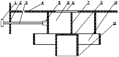
[0016] Such as figure 1 As shown, a special drainage and anti-blocking device for a kitchen sink includes a control handle 1, a fixed limit plate 2, a pull rod 3, a bottom surface of the sink 4, a fixed head 5, a feeding port 6, a sliding tank body 7, a garbage tank 8, a filter Water net 9, discharge port 10, drain port 11.

[0017] The sliding tank body 7 is placed between the bottom surface of the water tank 4 and the water filter net 9, the bottom surface of the water tank 4 is provided with a discharge port 6 to put in garbage, the bottom of the water filter net 9 is a drain port 11, and the discharge port 10 is located on both sides of the drain port 11 , the space between the sliding tank body 7 is a garbage tank 8, and the garbage tank 8 can slide between the tank bottom 4 and the water filter 9, forming a double-station structure.

[0018] A fixed head 5 is arranged on the side of the sliding tank body 7, the fixed head 5 is connected with the control handle 1 through...

Embodiment 2

[0020] This embodiment discloses the working principle of a special drainage and anti-blocking device for kitchen sinks: under normal circumstances, a part of the sliding tank body 7 overlaps with the filter screen 9, and the kitchen waste generated can be stored in the garbage tank 8, and the water passes through the filter screen 9 and drain outlet 11 are discharged, remaining solid kitchen waste.

[0021] When the solid kitchen waste in the garbage trough 8 is nearly full, pull the control handle 1 to drive the sliding tank body 7 to move, and the sliding tank body currently filled with solid kitchen waste moves to the discharge port 10. The sliding groove body 7 of the kitchen waste and the discharge port 10 form a fully open channel, and the solid kitchen waste is discharged through the discharge port 10, thereby achieving timely cleaning of the food waste in the sliding tank body in the water tank.

[0022] The present invention adopts a sliding double-station garbage ta...


PUM


Abstract

The invention discloses a drainage anti-blocking device special for kitchen sinks, and belongs to the field of garbage cleaning devices. The drainage anti-blocking device comprises a sliding slottingmechanism, wherein the sliding slotting mechanism comprises a sliding groove body, a fixing head, a pull rod and a control handle, a garbage groove is formed in the space in the sliding groove body, and a drainage discharging device is arranged at the lower part of the garbage groove. According to the drainage anti-blocking device, the sliding type double-station garbage groove is adopted to holdand collect garbage, the trouble of manual re-cleaning is avoided, garbage in the groove can be easily cleaned through the control handle, and convenience and rapidness are achieved. The solid kitchenwaste in the water tank after adopting the drainage anti-blocking device can be discharged in time and collected in a centralized manner, the liquid in the kitchen waste is reduced to escape everywhere, the peculiar smell is greatly reduced, and the separated solid kitchen waste can be widely applied to feed processing and field returning fertilization after being refined and collected, so that the problem of sanitary problem and high-value utilization of kitchen waste is solved.

Description

technical field [0001] The invention relates to the field of garbage cleaning devices, and more specifically, to a special drainage and anti-blocking device for kitchen sinks. Background technique [0002] Kitchen waste is a mixture of various food leftovers produced by people in the process of food processing in the kitchen. The types involve plant roots, meat scraps, bones, melon and fruit skins, etc., with complex components and different physical properties. The gathering place of these garbage mainly exists in the sink of the kitchen. During the process of kitchen waste generation, it usually enters the drain pipe through the filter device of the sink. Excessive amount and miscellaneous garbage usually cause the blockage of the sink drain pipe. And this kind of garbage is a collection of various organic matter. If it exists in a humid environment for a long time, it will rot and deteriorate, causing the accumulation of bacteria, causing environmental pollution in the ki...

Claims


Application Information

Patent Timeline
Patent Type & Authority Applications(China)
IPC IPC(8): E03C1/22E03C1/264
CPCE03C1/22E03C1/264
Inventor 曾广胜江太君孟聪胡灿陈一
Owner HUNAN UNIV OF TECH
Why Eureka
Try Eureka