
Wind-proof sand-blocking device and wind-proof sand-blocking system

A technology of sand-blocking, wind-proof and dust-suppressing nets, applied in the direction of fences, building types, buildings, etc., can solve the problems of power generation reduction, digging, burial of protective fences, etc., to reduce disturbance, reduce impact, and ensure local effect of airflow

Pending Publication Date: 2020-03-17
SHANGHAI ELECTRICGROUP CORP +1
View PDF0 Cites 0 Cited by
  • Summary
  • Abstract
  • Description
  • Claims
  • Application Information

AI Technical Summary

Problems solved by technology

[0004] (1) Sand damage is serious. Sand damage is the greatest harm to desert thermal and photovoltaic power stations. Sand damage is a great threat to the protective fence around the project area. The wind and sand are persistent and cumulative, which can easily cause the protective fence to be buried and eroded etc. Once the sand enters the project area over the protective fence, it will cause destructive hazards to the infrastructure, equipment, and ground surface in the power station;
[0005] (2) Harm from strong winds. Strong winds occur frequently in desert areas. Strong winds can cause fatal damage to photothermal mirrors and photovoltaic modules, seriously affecting the safe operation of power stations;
[0006] (3) Dust hazard. Dust falls naturally in the power station area to form dust, which seriously restricts the conversion efficiency and lifespan of photothermal photovoltaic power generation. Dust reduces power generation by 7% to 35%. The "hot spot effect" is formed by uneven light reception, which seriously damages the life of photovoltaic modules

Method used


Image

  • Wind-proof sand-blocking device and wind-proof sand-blocking system
  • Wind-proof sand-blocking device and wind-proof sand-blocking system
  • Wind-proof sand-blocking device and wind-proof sand-blocking system

Examples


Embodiment Construction

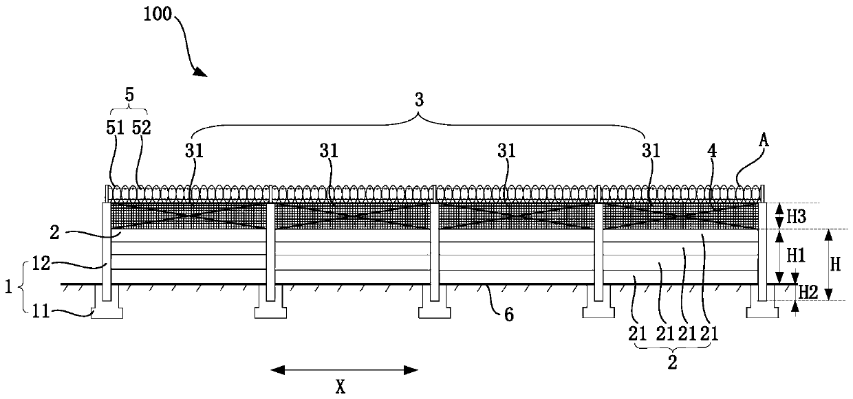
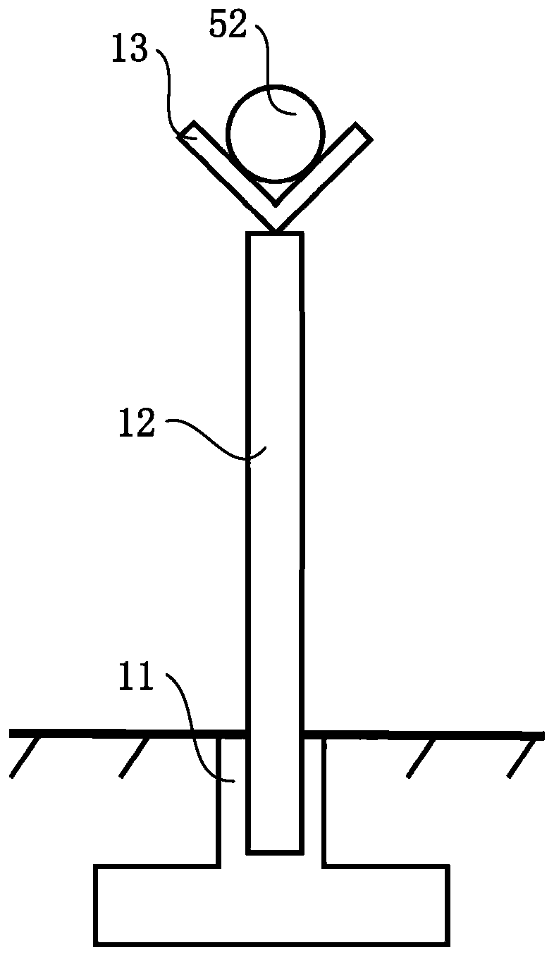
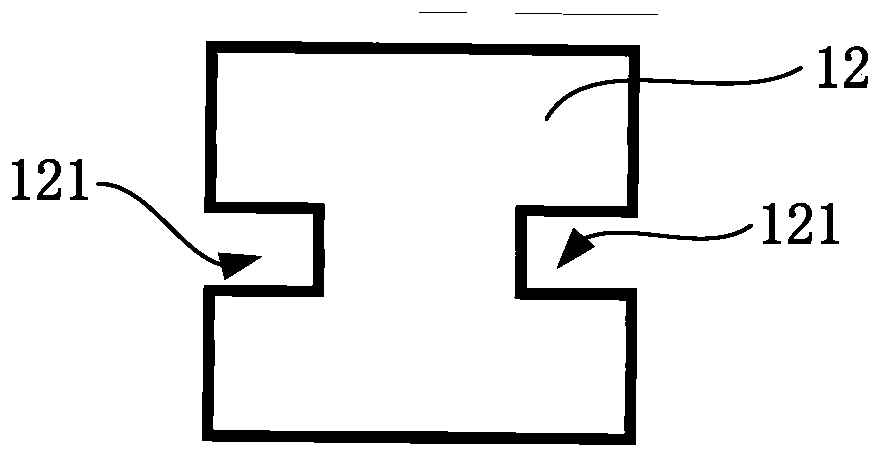
[0059] Combine below Figure 1 to Figure 13 The technical solution provided by the present invention is described in more detail.

[0060] Definitions of terms and terms used in this document.

[0061] Inside and outside refer to the inside and outside of the project area, the side facing the project area is the inside, and the side facing away from the project area is the outside. The windward side and the upwind direction are the side where the main wind direction passes first. like Figures 10-13 In the direction of the arrow, the direction pointed by the arrow is the direction of wind flow. The leeward side, the downwind direction, is the side where the main wind direction passes behind.

[0062]An embodiment of the present invention provides a wind and sand blocking device 100, which is suitable for photothermal photovoltaic power stations in desert areas. The wind and sand blocking device 100 includes an installation base 1 , a sand blocking part 2 and a net assembl...


PUM


Abstract

The invention discloses a wind-proof sand-blocking device and a wind-proof sand-blocking system, and relate to the field of wind sand prevention and control. The wind-proof sand-blocking device and the wind-proof sand-blocking system are used for optimizing the performance of the wind-proof sand-blocking device. The wind-proof sand-blocking device comprises a plurality of installation bases arranged at intervals, sand blocking parts and net assemblies. The sand blocking parts are constructed in a structure without holes, and are installed on the installation bases; the net assemblies are located above the sand blocking parts, and are fixedly connected with the installation bases or the sand blocking parts; the net assemblies include through holes; at least one sand blocking part and one net assembly are arranged between every two adjacent installation bases; and the height of the net assemblies is 0.3-0.8 of the height of the sand blocking parts below the net assemblies. According to the technical scheme, while sand blocking, wind blocking and dust suppression are effective, disturbance to wind and sand flow can be reduced to the maximum extent, local airflow stability can be guaranteed to the maximum extent, and influence on a project area is reduced.

Description

technical field [0001] The invention relates to the field of wind and sand prevention, in particular to a wind and sand prevention device and a wind and sand prevention system. Background technique [0002] As a renewable and clean energy source, solar power has developed rapidly all over the world in recent years. Desert areas have the advantages of abundant solar energy resources and cheap land, making large-scale desert thermal and photovoltaic power plants one of the main types of development in this industry. [0003] The inventor found that due to the natural environment in desert areas, the following problems generally exist in large-scale desert thermal and photovoltaic power plants: [0004] (1) Sand damage is serious. Sand damage is the greatest harm to desert thermal and photovoltaic power stations. Sand damage is a great threat to the protective fence around the project area. The wind and sand are persistent and cumulative, which can easily cause the protective ...

Claims


Application Information

Patent Timeline
Patent Type & Authority Applications(China)
IPC IPC(8): E04H17/00E04H17/04E04H17/06E04H17/08E04H17/10
CPCE04H17/00E04H17/04E04H17/066E04H17/08E04H17/10
Inventor 肖建华姚正毅屈建军谢小松刘明华赵辉马歆炜陈灿栗树果温换玲单艳花王玉林谷晓阳孙银波刘川杨流墨
Owner SHANGHAI ELECTRICGROUP CORP
Learn More