Valve processing equipment

A technology for processing equipment and valves, which is applied in the direction of metal processing equipment, metal processing, drilling/drilling equipment, etc., can solve the problem of low drilling efficiency of the valve body 1, and achieve the effect of improving efficiency

Active Publication Date: 2020-03-20
台州鑫宇铜业股份有限公司
View PDF6 Cites 5 Cited by
  • Summary
  • Abstract
  • Description
  • Claims
  • Application Information

AI Technical Summary

Problems solved by technology

[0004] When using the above-mentioned equipment to drill the valve, the worker needs to place the valve body 1 on the placement table 23, and make the side of the groove 11 face up, and then the worker uses the drilling machine 21 to make the drill bit perpendicular to the valve The middle part of the body 1 is drilled to form the required through hole 13, and then the worker takes down the processed valve and processes the next valve; the process of using this processing equipment to drill the valve In the process, workers are required to place the valves one by one on the placement table 23, and after the drilling is completed, they are taken off from the placement table 23 one by one. The manual drilling process is completely adopted in the whole drilling process. Hole processing efficiency is low

Method used


Image

  • Valve processing equipment
  • Valve processing equipment
  • Valve processing equipment

Examples


Embodiment Construction

[0037]The present invention will be described in further detail below in conjunction with the accompanying drawings.

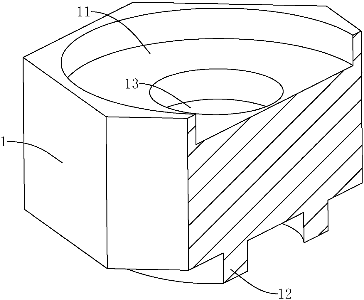
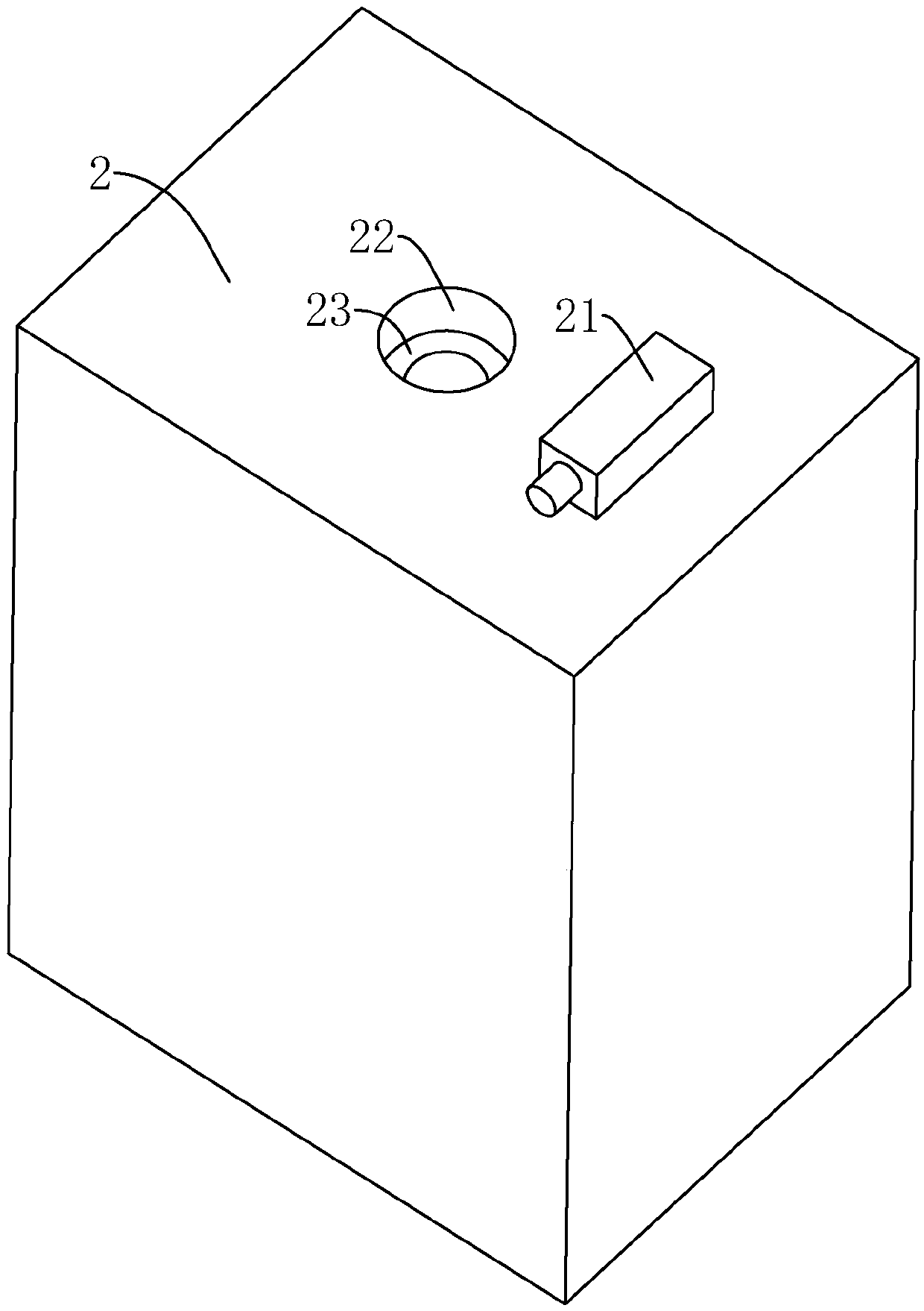
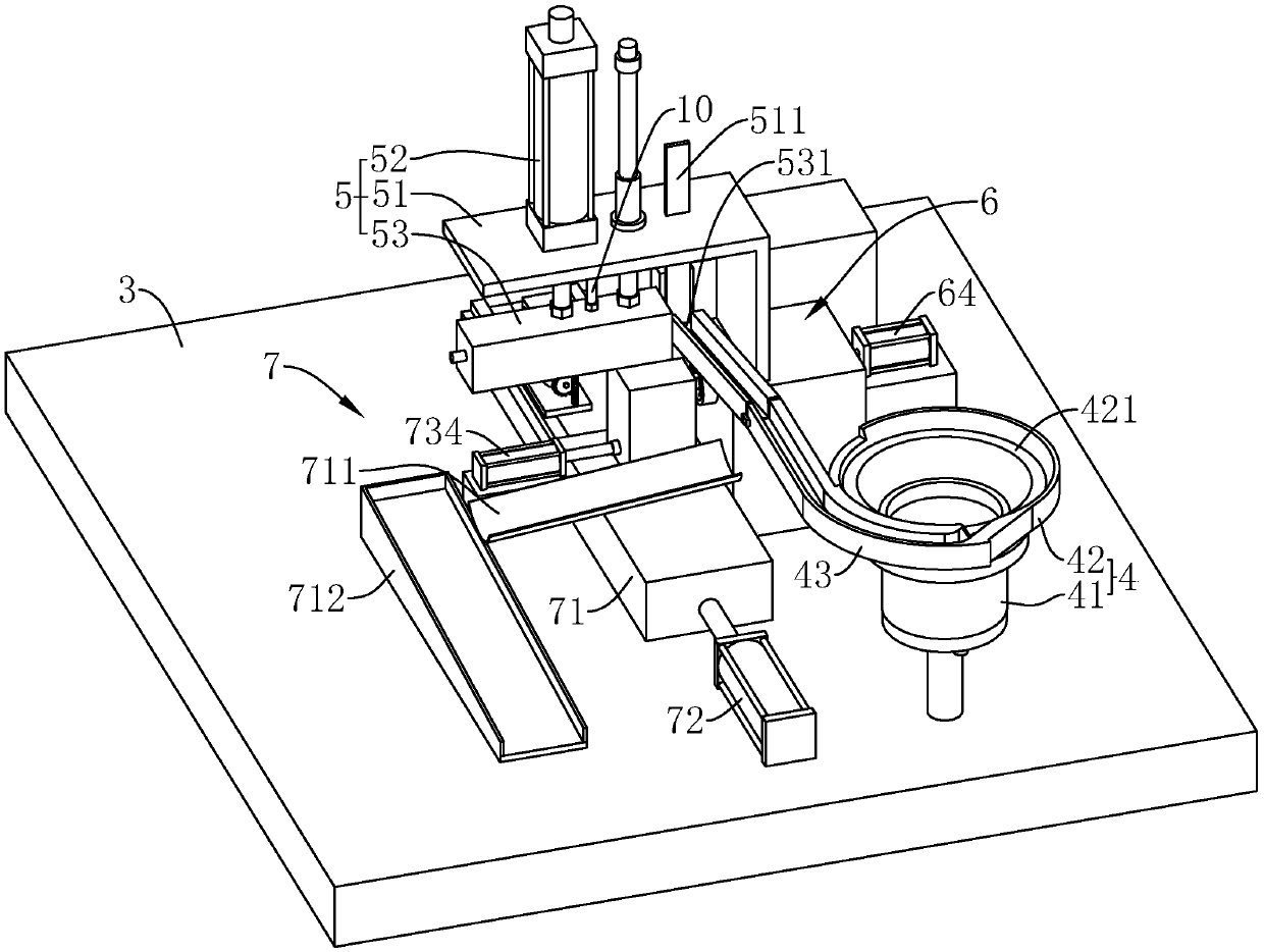
[0038] see image 3 , a valve processing equipment, comprising a frame 3, a feeding mechanism 4 arranged on the frame 3, a pushing mechanism 5 arranged on one side of the feeding mechanism 4, and a clamping mechanism 6 arranged below the pushing mechanism 5, a drill Hole mechanism7.

[0039] The feeding mechanism 4 includes a vibrating table 41 and a spiral vibrating disc 42 arranged in the vibrating table 41. The vibrating table 41 is used to drive the vibrating disc 42 to vibrate. Road 421, the outer wall of the vibrating plate 42 top is provided with a discharge part 43 connected with the feeding channel 421; the valve to be processed is placed on the vibrating plate 42, and the vibrating table 41 is opened to drive the vibrating plate 42 to vibrate so that the valve enters In the feeding channel 421 and gradually conveyed to the discharge part 43, the di...


PUM


Abstract

The invention discloses valve processing equipment, and relates to the field of valve processing. According to the technical scheme, the valve processing equipment is characterized by comprising a rack, a feeding mechanism, a pushing mechanism, a clamping mechanism and a drilling mechanism; the feeding mechanism comprises a vibrating table and a vibrating disc, a feeding channel is arranged in thevibrating disc, and a discharging part is arranged on the outer side wall of the vibrating disc; the pushing mechanism comprises a workbench, a first air cylinder and a pushing block, one end of thepushing block is provided with a receiving groove, the receiving groove communicates with the discharging part, and a pushing assembly is arranged on the side wall of the pushing block; the clamping mechanism comprises a clamping table, a clamping opening, a clamping assembly and a pushing piece; and the drilling mechanism comprises a sliding table, a second air cylinder and a drilling assembly, and the second air cylinder drives the sliding table to move, so that the drilling assembly faces a discharge port to drill a valve. Through the pushing mechanism, the clamping mechanism and the drilling mechanism, workers can automatically drill and form the valve only by putting the valve into the vibrating table, and the efficiency of valve drilling is improved.

Description

technical field [0001] The invention relates to the field of valve processing, in particular to a valve processing equipment. Background technique [0002] Common valves such as figure 1 As shown, the valve body 1 is included. A groove 11 is opened on one end surface of the valve body 1 , and an annular protrusion 12 extends on the other end surface. A through hole 13 is provided through the middle of the groove bottom of the groove 11 . [0003] During the processing of the above-mentioned valve, the valve body 1 needs to be drilled to form the required through hole 13. The existing equipment for processing the through hole 13 on the valve is as follows: figure 2 As shown, it includes a machine platform 2 and a drilling machine 21. A placement hole 22 runs through the machine platform 2. A placement platform 23 is provided on the wall of the placement hole 22. The distance from the placement platform 23 to the top surface of the machine platform 2 is smaller than the valv...

Claims


Application Information

Patent Timeline
IPC IPC(8): B23B41/00B23B47/00B23Q7/00B23Q7/06B23Q7/08
CPCB23B41/00B23B47/00B23Q7/00B23Q7/06B23Q7/08
Inventor 吴宇
Owner 台州鑫宇铜业股份有限公司
Why Eureka
Try Eureka