An Anti-magnetic Interference Bracket Applied to Hall Thruster Cluster

A magnetic interference and thruster technology, applied in the field of plasma, can solve the problems of affecting, affecting the discharge current and coupling voltage drop, affecting the acceleration of working medium ionized ions, etc., achieving flexible structure, reducing space magnetic flux leakage, and wide application range wide effect

Active Publication Date: 2021-02-19
HARBIN INST OF TECH
View PDF2 Cites 0 Cited by
  • Summary
  • Abstract
  • Description
  • Claims
  • Application Information

AI Technical Summary

Problems solved by technology

[0003] However, since the space that the satellite platform can provide for the thruster module is extremely limited, for the thruster cluster, the arrangement of each thruster unit is relatively concentrated, and the magnetic flux leakage around the thruster and its mutual coupling will affect the magnetic field distribution of the thruster unit. It has a non-negligible impact, which has become one of the key factors restricting the overall performance of the thruster cluster
When the magnetic field distribution in the thruster discharge chamber is affected, it is difficult to establish an efficient electrical conductivity and potential distribution in the channel, which in turn affects the ionization of the working fluid and the acceleration of ions
At the same time, due to the mutual coupling of the thruster's external magnetic field, the electron path emitted by the cathode may be affected, which in turn affects the discharge current and coupling voltage drop, and negatively affects the acceleration of ions and critical plasma parameters.

Method used


Image

  • An Anti-magnetic Interference Bracket Applied to Hall Thruster Cluster
  • An Anti-magnetic Interference Bracket Applied to Hall Thruster Cluster
  • An Anti-magnetic Interference Bracket Applied to Hall Thruster Cluster

Examples


Embodiment Construction

[0030] It should be noted that, in the case of no conflict, the embodiments of the present invention and the features in the embodiments can be combined with each other.

[0031] The present invention will be described in detail below with reference to the accompanying drawings and examples.

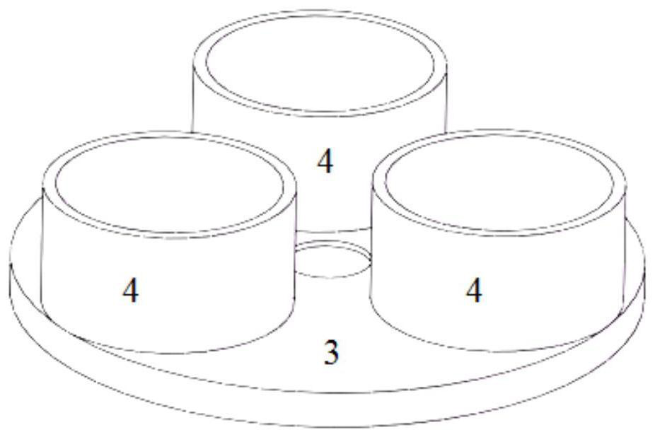
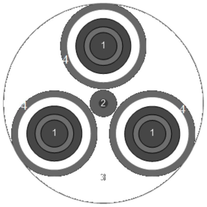
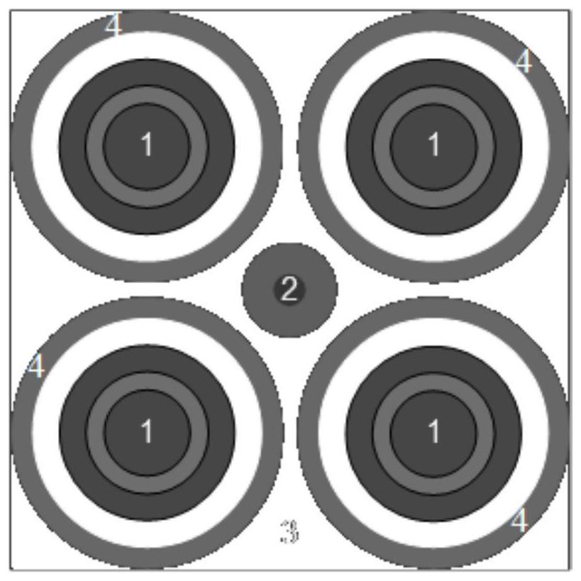
[0032] Such as Figure 1-Figure 3 As shown, a kind of anti-magnetic interference bracket applied to the Hall thruster cluster includes a magnetic base plate 3 and a plurality of magnetic sleeves 4 evenly arranged on the magnetic base plate 3, the magnetic base plate 3 and multiple Two magnetically conductive sleeves 4 are integrally formed, and each magnetically conductive sleeve 4 is equipped with a thruster unit 1 of the Hall thruster cluster, and each magnetically conductive sleeve 4 completely blocks the thruster unit 1 therein. The magnetic sleeves 4 are all provided with gaps, the center of the area surrounded by a plurality of magnetic sleeves 4 is the center of the magnetic bott...


PUM

PropertyMeasurementUnit
thicknessaaaaaaaaaa

Abstract

The invention provides an anti-magnetic interference bracket applied to Hall thruster clusters, which includes a magnetically conductive bottom plate and a plurality of magnetically conductive sleeves evenly arranged on the magnetically conductive bottom plate, and the magnetically conductive bottom plate and the plurality of magnetically conductive sleeves are integrated Forming setting, a thruster unit of the Hall thruster cluster is placed in each magnetic sleeve, each magnetic sleeve completely covers the thruster unit inside, and there are gaps between each magnetic sleeve, multiple The center of the area enclosed by the magnetic sleeve is the center of the magnetic bottom plate, and the cathode is arranged in the center of the area enclosed by multiple magnetic sleeves, and the cathode is the shared cathode of each thruster unit of the Hall thruster cluster. The anti-magnetic interference support of the present invention can effectively reduce the spatial magnetic flux leakage of the thruster while fixing each thruster unit, so as to ensure that each thruster unit is free from external magnetic field interference. At the same time, a cathode can be arranged in the center of the bracket, and a cathode sharing strategy can be adopted to provide electrons required for the ionization process and ion neutralization process for several thrusters at the same time.

Description

technical field [0001] The invention belongs to the fields of aerospace electric propulsion technology and plasma technology, and in particular relates to an anti-magnetic interference bracket applied to a Hall thruster cluster. Background technique [0002] With the development of space electric propulsion technology and the introduction of all-electric propulsion technology, the electric thruster has gradually expanded from a single auxiliary propulsion to the main propulsion, and its functions have moved from simplification to diversification. The diversification of future space missions requires electric thrusters to work stably with high performance within a wide range of parameter changes, but it is still difficult for a single Hall thruster to meet the application requirements. The proposal and application of the concept of the Hall thruster cluster (a thruster group composed of two or more thruster units) has effectively expanded the thrust adjustment range and impro...

Claims


Application Information

Patent Timeline
Patent Type & Authority Patents(China)
IPC IPC(8): F03H1/00
CPCF03H1/0075
Inventor 丁永杰李鸿范昊天魏立秋于达仁
Owner HARBIN INST OF TECH
Why Eureka
Try Eureka