Furnace end of combustor

A burner and burner technology, applied in the direction of burners, gas fuel burners, combustion methods, etc., can solve the problems of unfavorable development, affecting the service life of the burner, and low working reliability, so as to reduce poor process stability and reduce The effect of unreliable quality and high work reliability

Pending Publication Date: 2020-03-20
陈毅
View PDF0 Cites 0 Cited by
  • Summary
  • Abstract
  • Description
  • Claims
  • Application Information

AI Technical Summary

Problems solved by technology

However, the furnace head as a whole is basically cast iron or cast aluminum structure. The casting process of cast iron or aluminum alloy casting process, the second process of burning molten iron requires coal burning, sand core manufacturing, and cavity cleaning. Sand cleaning and other dusty, mass production A large production site is often required, and the production environment is not good. Long-term development is not conducive to the development of the industry and the protection of the ecological environment.
[0003] In the early stage, there were stainless steel burners in the market, but they were basically used for desktop gas stoves. However, due to the unreasonable use of base structures or materials, and with the upgrading of consumption, the proportion of desktop gas stoves in the entire market has been declining year by year. , so it has not been well promoted
[0004] In the early stage, there were also stainless steel burners for embedded stoves on the market, but the mai...

Method used


Image

  • Furnace end of combustor
  • Furnace end of combustor
  • Furnace end of combustor

Examples


Embodiment 1

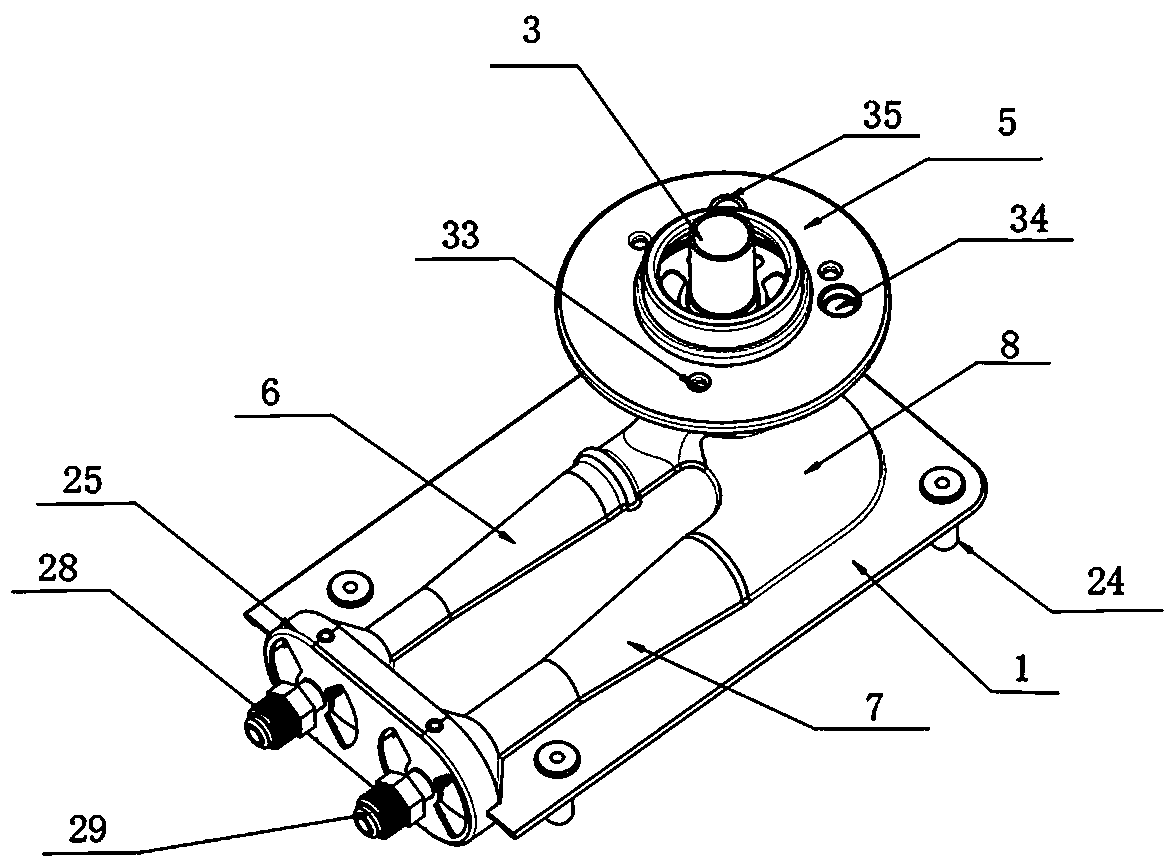
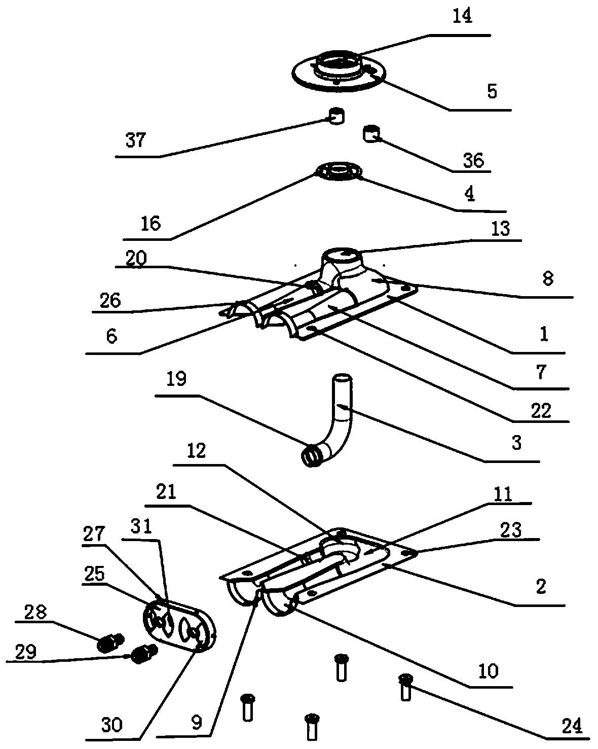
[0046] refer to Figure 1-Figure 5 , the furnace head of the burner, including the upper cover 1, the lower bottom 2, the central mixing nozzle 3, the connecting pipe fixing plate 4, the mounting flange 5, the upper cover 1 is covered on the lower bottom 2, and the upper cover 1 is provided with a central fire starter Ejector upper half 6, main fire ejector upper half 7 and main fire upper half cover 8, lower bottom 2 is provided with center fire ejector lower half 9, main fire ejector lower half 10 and The lower half cover 11 of the main fire, the upper half 6 of the center fire ejector is covered on the lower half 9 of the center fire ejector, the upper half 6 of the center fire ejector and the lower half 9 of the center fire ejector jointly constitute Central fire ejector, the main fire ejector upper half 7 is covered on the main fire ejector lower half 10, and the main fire ejector upper half 7 and the main fire ejector lower half 10 jointly constitute the main fire ejecto...

Embodiment 2

[0065] The difference between this embodiment and embodiment 1 is:

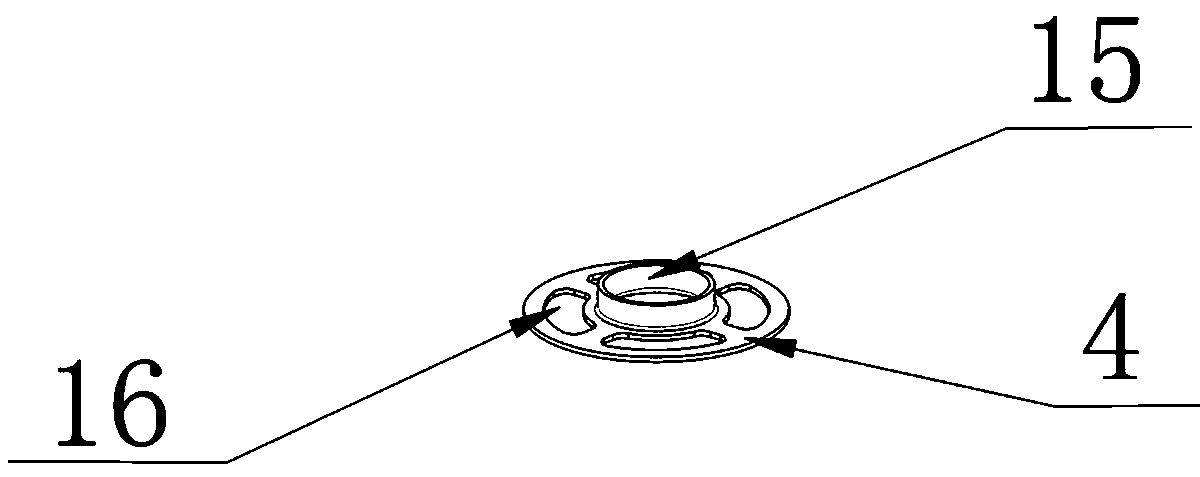
[0066] refer to Figure 6-Figure 11 , in this embodiment, the upper half cover 8 of the main fire is connected with the installation flange 5 through the flange seat 17, the flange seat 117 is arranged between the installation flange 5 and the upper half cover 8 of the main fire, and the flange seat 17 is fixed on On the upper half cover 8 of the main fire, the mounting flange 5 is covered on the flange seat 17, and the center of the flange seat 17 has a through hole 18, and the center through hole 18 of the flange seat 17 is connected with the upper half cover 8 of the main fire. The through hole 13 communicates, and the fixed plate 4 is arranged on the inner wall top of the central through hole 18 of the flange seat 17. The central through hole 15 of the fixed plate 4 and the air-distributing through hole 16 all pass through the central through hole 18 of the flange seat 17 and The through hole 13 on the u...


PUM

PropertyMeasurementUnit
Thicknessaaaaaaaaaa

Abstract

The invention discloses a furnace end of a combustor, which comprises an upper cover, a lower bottom, a central mixing connecting pipe, a connecting pipe fixing disc and a mounting flange, wherein theupper cover covers the lower bottom; the upper cover is provided with a central fire ejector upper half part, a main fire ejector upper half part and a main fire upper half cover; the lower bottom isprovided with a central fire ejector lower half part, a main fire ejector lower half part and a main fire lower half cover; the central fire ejector upper half part and the central fire ejector lowerhalf part jointly form a central fire ejector; the main fire ejector upper half part and the main fire ejector lower half part jointly form a main fire ejector; a cavity defined by the main fire upper half cover and the main fire lower half cover is a main fire mixing cavity; the lower end of the center mixing connecting pipe penetrates through the main fire mixing cavity and then stretches intothe outlet end of the center fire ejector; and the upper end of the center mixing connecting pipe sequentially penetrates through a through hole in the main fire upper half cover, a center through hole of the connecting pipe fixing disc and a center through hole of the mounting flange from bottom to top and then stretches out to the position above the center through hole of the mounting flange. The space utilization rate is high, and the working reliability is high.

Description

technical field [0001] The invention relates to a stove head of a burner. Background technique [0002] At present, in the industry of gas cookers and integrated cookers, the traditional aircraft-type burners (or Siemens or cherry blossom burners) have been used for a large proportion because of their low price and good stability. Indispensable accessories for this industry application. However, the furnace head as a whole is basically cast iron or cast aluminum structure. The casting process of cast iron or aluminum alloy casting process, the second process of burning molten iron requires coal burning, sand core manufacturing, and cavity cleaning. Sand cleaning and other dusty, mass production A large production site is often required, and the production environment is not good. Long-term development is not conducive to the development of the industry and the protection of the ecological environment. [0003] In the early stage, there were stainless steel burners in the m...

Claims


Application Information

Patent Timeline
IPC IPC(8): F23D14/04F23D14/46F23D14/64
CPCF23D14/04F23D14/46F23D14/64
Inventor 陈毅周国来
Owner 陈毅
Why Eureka
Try Eureka