
Flue gas deacidification and dust removal system

A dust removal system and flue gas technology, applied in gas treatment, dispersed particle filtration, membrane technology, etc., can solve the problems of dew condensation on the surface of the cloth bag, low flue gas temperature, sticking of the bag, etc., to increase the processing capacity, improve the processing efficiency, The effect of improving efficiency

Pending Publication Date: 2020-03-24
XIAN XIKUANG ENVIRONMENTAL PROTECTION
View PDF11 Cites 1 Cited by
  • Summary
  • Abstract
  • Description
  • Claims
  • Application Information

AI Technical Summary

Problems solved by technology

[0003] The purpose of the present invention is to overcome the deficiencies of the prior art and provide a flue gas deacidification and dust removal system applied to waste incineration flue gas to solve the problem of low flue gas temperature when the incinerator is working abnormally. Problems of surface condensation and bag sticking

Method used


Image

  • Flue gas deacidification and dust removal system

Examples


Embodiment 1

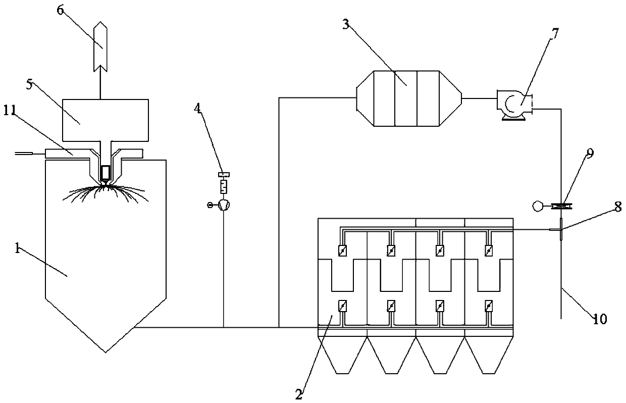
[0025] As a kind of flue gas deacidification and dust removal system of the embodiment of the present invention, such as figure 1 As shown, the flue gas deacidification and dust removal system includes a deacidification tower 1, a slurry tank 6, a dry powder injection device 4, a bag filter 2, an electric duct heater 3, a rotary atomizer 5 and a fan 7;

[0026] The deacidification tower 1 is provided with a flue gas inlet, a slurry inlet and a flue gas outlet. The flue gas inlet of the deacidification tower 1 is a spiral flue gas inlet 11, and the spiral flue gas inlet 11 is provided with deflectors. The diversion direction is opposite to the spray tangential direction of the rotary atomizer 5. The rotary atomizer 5 has a slurry inlet and a slurry outlet. The slurry inlet of the rotary atomizer 5 is connected to the slurry tank 6. The slurry of the rotary atomizer 5 The outlet is connected to the slurry inlet pipeline of the deacidification tower 1;

[0027] The bag filter 2 ...


PUM


Abstract

The invention provides a flue gas deacidification and dust removal system. The flue gas deacidification and dust removal system comprises a deacidification tower, a slurry tank, a dry powder injectiondevice, a bag type dust collector and a circulating heater, wherein the slurry tank, the deacidification tower and the bag type dust collector are sequentially communicated, a dry powder injection port is connected to a pipeline between a flue gas outlet of the desulfurization tower and a gas inlet of the bag type dust collector, a gas outlet of the bag type dust collector is communicated with agas inlet pipeline of the circulating heater, and a gas outlet of the circulating heater is communicated with a gas inlet pipeline of the bag type dust collector. According to the flue gas deacidification and dust removal system, flue gas exhausted by an incinerator is treated when the incinerator works abnormally, the situations that dew is formed on the surface of a cloth bag of the bag type dust collector, the cloth bag is pasted and corroded by acids are avoided, exhausted gas does not contain dust, and the removal efficiency of acid pollutants in the flue gas subjected to cyclic heating treatment is higher.

Description

technical field [0001] The invention relates to the technical field of flue gas treatment equipment, in particular to a flue gas deacidification and dust removal system. Background technique [0002] Waste incineration flue gas contains a variety of pollutants: acid pollutants, dust, NO x , dioxins and heavy metal pollutants, acid pollutants (mainly HCl, HF, SO 2 ) and dust (small particle size, high viscosity), most engineering projects use semi-dry method (Ca(OH) 2 ) deacidification + bag dust removal process to treat the flue gas, but during the start-up and shutdown of the incinerator, abnormal situations or during boiler commissioning, due to the low exhaust gas temperature of the boiler, it is not suitable to spray lime slurry, and the semi-dry deacidification system cannot work normally. Putting it into operation will cause dew condensation on the surface of the bag filter and the problem of bag sticking will be serious. Contents of the invention [0003] The pur...

Claims


Application Information

Patent Timeline
Patent Type & Authority Applications(China)
IPC IPC(8): B01D53/75B01D53/80B01D53/81B01D46/02B01D53/50B01D53/56B01D53/60B01D53/68
CPCB01D53/75B01D53/80B01D53/81B01D46/023B01D53/60B01D53/56B01D53/502B01D53/50B01D53/68B01D53/685B01D2251/404B01D2251/604B01D2257/302B01D2257/404B01D2257/2045B01D2257/2047B01D2258/0283
Inventor 祝文樊彦玲陈贵福郑鹏辉沈建涛谭光之许荣胜
Owner XIAN XIKUANG ENVIRONMENTAL PROTECTION
Learn More