
Rust-proof rotary air cylinder air pressure clamping device for machining engine oil shell body

A technology of rotating cylinders and clamping equipment, which is applied in the direction of metal processing equipment, metal processing machinery parts, clamping devices, etc., can solve problems such as oxidation and rust, insufficient technical considerations, and influence on the accuracy of the oil casing, so as to ensure firmness The effect of improving durability, improving firmness and improving production quality

Active Publication Date: 2020-03-24
绍兴欣耀机电科技有限公司
View PDF12 Cites 0 Cited by
  • Summary
  • Abstract
  • Description
  • Claims
  • Application Information

AI Technical Summary

Problems solved by technology

[0002] The oil pump is the heart of the automobile fuel system, which determines the overall performance of the engine. In the manufacturing process of the oil pump, the oil casing is the main processing part. In order to speed up the production efficiency of the oil casing, the rotary clamping cylinder is selected to hold the workpiece Turning and milling after fixing, but the current technical considerations are not perfect, and has the following disadvantages: the oil casing will generate a lot of heat during the turning and milling process, so an air conditioner is installed in the processing workshop to cool down, but the pipe connection of the rotary clamping cylinder The temperature of the head drops rapidly under the action of cold air, and the inner wall of the pipe will undergo liquefaction reaction to form condensate, and form bubbles under the action of air pressure. As the gas enters the interior of the cylinder, the inner wall of the cylinder will be oxidized and rusted, reducing the clamping force of the oil cover. Robustness, while affecting the machining accuracy of the oil housing

Method used


Image

  • Rust-proof rotary air cylinder air pressure clamping device for machining engine oil shell body
  • Rust-proof rotary air cylinder air pressure clamping device for machining engine oil shell body
  • Rust-proof rotary air cylinder air pressure clamping device for machining engine oil shell body

Examples


Embodiment

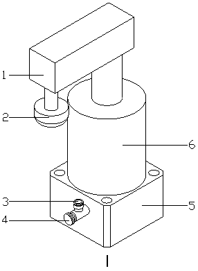
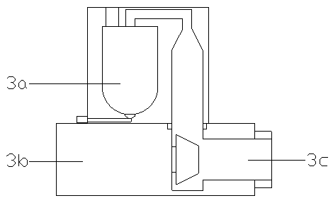
[0024] see Figure 1-Figure 2 , the present invention provides a rust-proof rotary cylinder pneumatic clamping device for processing engine oil shells. , Cylinder main body 6, the bottom of the fixed support base 5 and the upper surface of the processing table are fixed together by bolts, the cylinder main body 6 is located above the fixed support base 5 and has an integrated structure with the fixed support base 5, the air pressure connection pipeline 3. The right end is connected to the left side of the fixed support seat 5 by a sealed connection. The throttle valve 4 is located on the left side of the air pressure connection pipe 3 and is interlocked with the air pressure connection pipe 3. The bottom of the housing clamping frame 1 is connected to the inner wall of the cylinder body 6. With clearance fit, the inner wall of the buffer block 2 is bonded to the bottom of the left end of the housing clamping frame 1. The air pressure connecting pipe 3 is composed of a water va...


PUM


Abstract

The invention discloses a rust-proof rotary air cylinder air pressure clamping device for machining an engine oil shell body. The rust-proof rotary air cylinder air pressure clamping device structurally comprises a shell body clamping frame, a buffer block, an air pressure connecting pipeline, a throttle valve, a fixed supporting seat and an air cylinder main body, the fixed supporting seat and amachining platform are fixed together through bolts, the air cylinder main body and the fixed supporting seat are of an integrated structure, and the air pressure connecting pipeline is connected withthe fixed supporting seat in a sealed mode. According to the rust-proof rotary air cylinder air pressure clamping device, a moisture discharging device is installed, before the high-pressure gas is input into an air cylinder, a condensate can be effectively separated from the gas, the situation that the condensate forms bubbles and enters the air cylinder, and thus oxidation and rust of the air cylinder are caused is avoided, the clamping firmness of the clamping device to an engine oil cover body is ensured, and the production quality of the engine oil shell body is improved.

Description

technical field [0001] The invention relates to a pneumatic device, in particular to a rust-proof rotary cylinder pneumatic clamping device for processing engine oil casings. Background technique [0002] The oil pump is the heart of the automobile fuel system, which determines the overall performance of the engine. In the manufacturing process of the oil pump, the oil casing is the main processing part. In order to speed up the production efficiency of the oil casing, the rotary clamping cylinder is selected to hold the workpiece Turning and milling after fixing, but the current technical considerations are not perfect, and has the following disadvantages: the oil casing will generate a lot of heat during the turning and milling process, so an air conditioner is installed in the processing workshop to cool down, but the pipe connection of the rotary clamping cylinder The temperature of the head drops rapidly under the action of cold air, and the inner wall of the pipe will ...

Claims


Application Information

Patent Timeline
IPC IPC(8): B23Q3/08B23Q11/00
CPCB23Q3/062B23Q3/08B23Q11/00B23Q2703/04
Inventor 凌金霞
Owner 绍兴欣耀机电科技有限公司
Learn More