
Quartz slotted rod slotting device

A technology of slotting equipment and slotted bar, applied in the field of quartz slotted bar slotting equipment, can solve the problems of difficulty in taking out the quartz slotted bar, uneven slotting position, fracture of the quartz slotted bar, etc. The effect of improving work efficiency

Inactive Publication Date: 2020-03-24
浙江鸿达石英电子科技有限公司
View PDF7 Cites 0 Cited by
  • Summary
  • Abstract
  • Description
  • Claims
  • Application Information

AI Technical Summary

Problems solved by technology

[0003] At present, the grooving process of quartz grooved rods is usually to place the quartz grooved rods on the worktable of the CNC machine tool with V-shaped grooves to prevent the movement of the quartz grooved rods during the grooving process and reduce the groove accuracy.
In the actual processing process, the quartz groove rod is fixed in the V-shaped groove and is in a static state. The entire quartz groove rod is mainly moved by the groove device to perform groove processing. The work efficiency is low, and this fixed groove method makes the quartz groove The rod will vibrate slightly up and down during the slotting process, which may cause the slotting position to be uneven, or cause the quartz slotted rod to break as a whole; in order to reduce the temperature at the cutting slot during the slotting process, it is necessary to continuously The cooling liquid is sprayed at the groove position, and the cooling liquid is easy to enter the V-shaped groove, so that the connection between the quartz groove rod and the V-shaped groove is tight, and it is difficult to take out the quartz groove rod directly
[0004] Therefore, the existing slotting equipment for quartz slot rods has the problems of low work efficiency, unstable fixation, and difficulty in taking out the quartz slot rods.

Method used

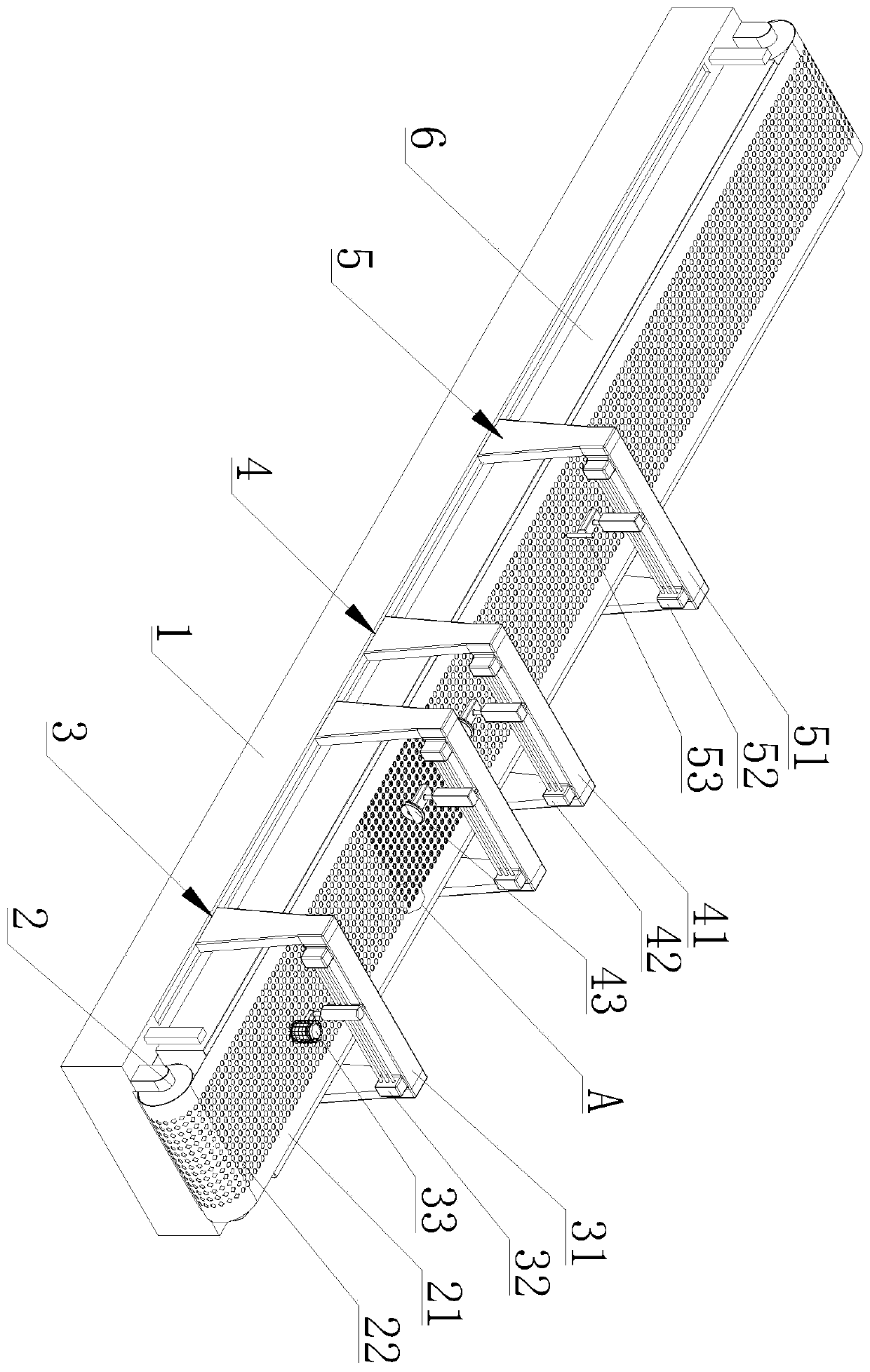
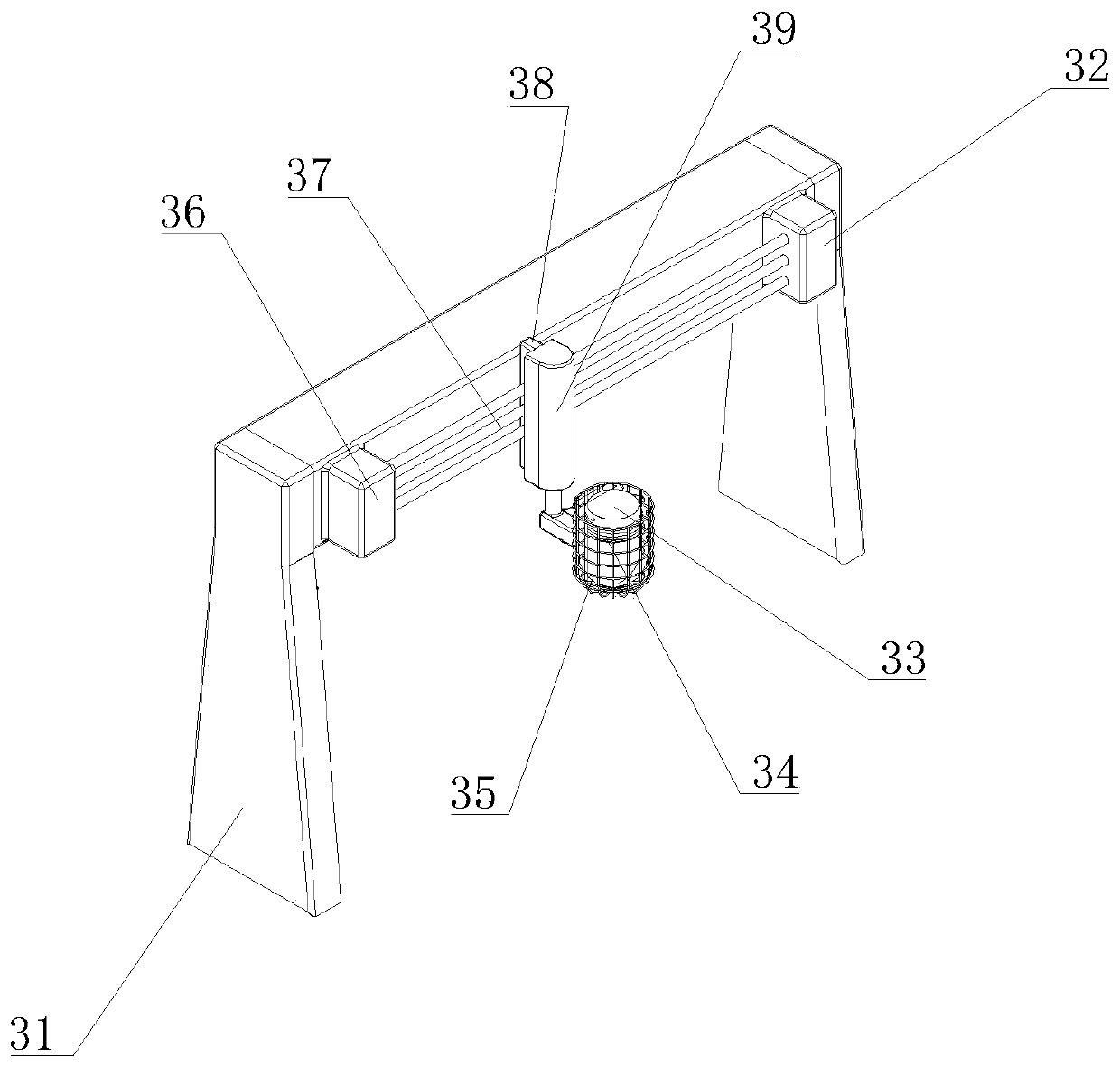
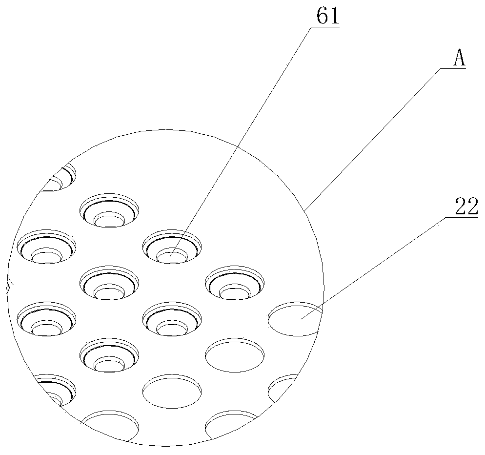

Image

  • Quartz slotted rod slotting device
  • Quartz slotted rod slotting device
  • Quartz slotted rod slotting device

Examples


Embodiment Construction

[0021] The present invention will be further described below in conjunction with the examples, but not as a basis for limiting the present invention.

[0022] Example.

[0023] like Figure 1-3 As shown, a quartz groove bar slotting equipment includes a base 1, on which a conveying device 2 is arranged, and a wax pouring device 3, a slotting device 4 and a wax melting device are sequentially slidably connected to the base 1 along the conveying direction 5. A working platform 6 is provided below the conveying device 2, and a number of vacuum suction cups 61 are provided on the working platform 6 corresponding to the slotting device 4.

[0024] The wax pouring device 3 comprises a wax pouring installation frame 31, a first two-dimensional moving device 32 is provided on the wax pouring installation frame 31, a wax pouring pot 33 is provided on the first two-dimensional mobile device 32, and the outer periphery of the wax pouring pot 33 A heating wire 34 is surrounded on the wa...


PUM


Abstract

The invention discloses a quartz slotted rod slotting device, which comprises a base (1), wherein a conveying device (2) is disposed on the base (1); a waxing device (3), a slotting device (4) and dewaxing device (5) are successively in sliding connection to the base (1) along the conveying direction; a working platform (6) is disposed below the conveying device (2); and a plurality of vacuum suction cups (61) are disposed on the working platform (6) at positions corresponding to the slotting device (4). The quartz slotted rod slotting device has high working efficiency, is stable, and can easily take out the quartz slotted rod.

Description

technical field [0001] The invention relates to a processing equipment for quartz grooved rods, in particular to a grooved equipment for quartz grooved rods. Background technique [0002] At present, in the semiconductor product manufacturing industry, quartz boats are widely used as wafer carriers in the semiconductor oxidation diffusion process. Multiple wafers can be inserted into the grooves of the groove rods for diffusion processing. Semiconductor silicon quality has a greater impact. Therefore, when the quartz boat is being processed, the grooving of the quartz groove rod is undoubtedly the most critical step. For the quartz longboat, the length of the quartz groove rod is relatively long, and how to position and fix the quartz groove rod during the slotting process is a difficult point, which will directly affect the quality and precision of the quartz groove rod after slotting. [0003] At present, the grooving process of the quartz grooved rod is usually to place...

Claims


Application Information

Patent Timeline
IPC IPC(8): B28D5/02B28D7/00B28D7/04
CPCB28D5/0058B28D5/0082B28D5/0094B28D5/023
Inventor 茅文犀
Owner 浙江鸿达石英电子科技有限公司
Learn More