Eureka AIR delivers breakthrough ideas for toughest innovation challenges, trusted by R&D personnel around the world.

Self-locking protection device for LED power supply

A technology of LED power supply and self-locking protection, applied in the direction of lighting devices, circuit layout, lighting device components, etc., can solve the problems of not being able to eliminate high temperature in time, not being able to effectively protect the circuit from overload and short circuit hazards, etc., and achieve high social use value and application prospects, avoiding failure expansion or causing fires, and reducing losses

Pending Publication Date: 2020-03-24
安徽润诚机电有限公司
View PDF0 Cites 0 Cited by
  • Summary
  • Abstract
  • Description
  • Claims
  • Application Information

AI Technical Summary

Problems solved by technology

[0004] The existing LED drive power supply has certain disadvantages in use. It cannot effectively protect the circuit from the damage caused by overload and short circuit, and cannot eliminate the internal high temperature in time, which has brought certain adverse effects to actual use.

Method used


Image

  • Self-locking protection device for LED power supply
  • Self-locking protection device for LED power supply
  • Self-locking protection device for LED power supply

Examples


Embodiment 1

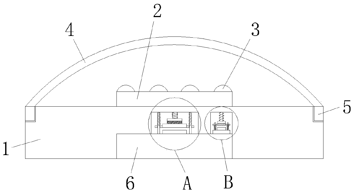
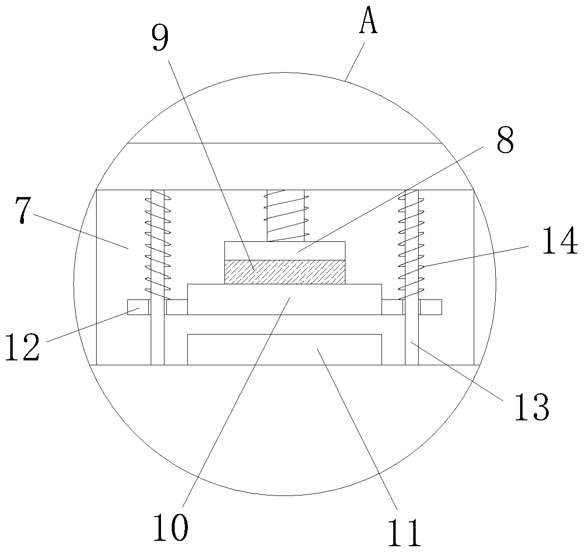
[0030] refer to figure 1 , Figure 3-5 , a LED power supply self-locking protection device, including a base 1, the upper end of the base 1 is provided with a PCB board 2, and the upper end of the PCB board 2 is provided with several groups of LED light sources 3, the inner wall of the base 1 is provided with an LED power supply 6, and the LED The upper end of the power supply 6 is provided with an installation chamber 7, the upper end wall of the installation chamber 7 is fixedly installed with a first electromagnet 8, and the bottom of the first electromagnet 8 is adsorbed with a magnet sheet 9, and the bottom of the magnet sheet 9 is fixedly connected with a first moving The contact piece 10 is provided with a first static contact piece 11 at the bottom of the installation cavity 7 and directly below the first moving contact piece 10 , and a first limiting block 12 is symmetrically provided on both side walls of the first moving contact piece 10 , And the inner wall of the...

Embodiment 2

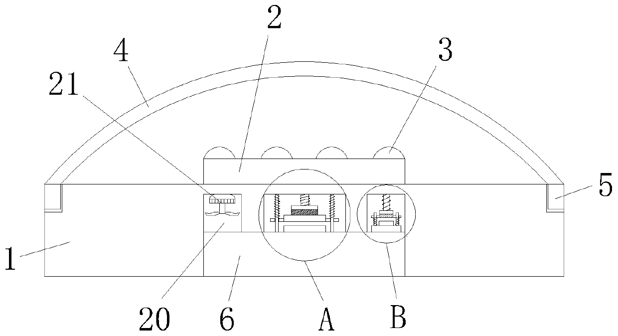
[0037] refer to Figure 2-5 The difference between this embodiment and Embodiment 1 is that, the inner wall of the base 1 and the upper end of the LED power supply 6 are provided with a second cavity 20, and the inner top wall of the second cavity 20 is fixedly installed with a cooling fan 21, when When the first moving contact piece 10 is closely attached to the first static contact piece 11 , the start switch of the cooling fan 21 is activated, so that the cooling fan 21 runs and starts to cool down the LED power supply 6 .

[0038] Refer to Example 1 for other undescribed structures.

[0039]Working principle: In the present invention, when in use, the LED power supply 6 supplies power to the PCB board 2 and the LED light source 3 to realize lighting; when the circuit is overloaded, the overload protector starts and disconnects the circuit switch. The electromagnet 8 loses its electrical connection, and the first electromagnet 8 loses its adsorption force to the magnet pie...


PUM


Abstract

The invention discloses a self-locking protection device for an LED power supply. The device comprises a base; a PCB is arranged at the upper end of the base; a plurality of groups of LED light sources are arranged at the upper end of the PCB; the LED power supply is arranged on the inner wall of the base; a mounting cavity is formed in the upper end of the LED power supply; a first electromagnetis fixedly mounted on the upper end wall of the mounting cavity; a magnet piece is attracted to the bottom of the first electromagnet; a first movable contact piece is fixedly connected to the bottomof the magnet piece; a first static contact piece located under the first movable contact piece is arranged at the bottom of the mounting cavity; a first supporting rod is perpendicularly inserted into the inner wall of a first limiting block; and the outer wall of the first supporting rod is sleeved with a first spring. With the self-locking protection device for the LED power supply of the invention, defects in the prior art are overcome; when the LED power supply undergoes an overload fault, the LED power supply achieves a self-locking prevention function; and a heat dissipation and coolingeffect is realized, so that the expansion of the fault or fire disasters can be avoided. The self-locking protection device for the LED power supply is reasonable in design and has high social use value and a bright application prospect.

Description

technical field [0001] The invention relates to the technical field of LEDs, in particular to an LED power supply self-locking protection device. Background technique [0002] With the development of technology, LED lights have a wide range of uses, and it will inevitably replace existing lighting devices. LED lights have the advantages of low power consumption and long service life, among which LED driving power plays a key role. [0003] LED drive power supply is a power converter that converts the power supply into a specific voltage and current to drive LED light. It is composed of IC control chips and so on. It has a good constant current output during use, stable protection of LED light emission and service life, and Low power consumption, widely used in various fields. [0004] The existing LED drive power supply has certain disadvantages in use, and cannot effectively protect the circuit from overload and short-circuit hazards, and cannot promptly eliminate the inte...

Claims


Application Information

Patent Timeline
Patent Type & Authority Applications(China)
IPC IPC(8): F21V25/04F21V23/04F21V29/508F21V29/60F21Y115/10
CPCF21V25/04F21V23/04F21V29/508F21V29/60F21Y2115/10
Inventor 李宗武徐宝金
Owner 安徽润诚机电有限公司
Why Eureka
Eureka Blog
Learn More