Check patentability & draft patents in minutes with Patsnap Eureka AI!

tactile sensor

A tactile sensor and photosensitive sensor technology, applied in the field of sensors, can solve the problems that tactile sensors are susceptible to external environment interference and have poor robustness, and achieve the effects of good linearity, diverse installation environments, and strong anti-interference ability.

Active Publication Date: 2021-01-05
INST OF AUTOMATION CHINESE ACAD OF SCI
View PDF9 Cites 0 Cited by
  • Summary
  • Abstract
  • Description
  • Claims
  • Application Information

AI Technical Summary

Problems solved by technology

[0004] In order to solve the above-mentioned problems in the prior art, that is, in order to solve the problem that the existing tactile sensor is easily disturbed by the external environment and the robustness is not strong, the present invention provides a tactile sensor, which includes: a rigidly connected bottom shell and a top Cover, a cavity is formed between the bottom case and the top cover, and the top cover is provided with a first through hole; a light source, an elastic and light-transmitting elastic member and a photosensitive sensor are arranged in the cavity; the light source The photosensitive sensor and the photosensitive sensor are respectively located on opposite sides of the elastic component; the photosensitive area of ​​the photosensitive sensor receives the light passing through the elastic component; the side of the elastic component away from the bottom shell is provided with a rigid and An opaque tactile part, the tactile part resists the bottom shell and the top cover, and the tactile part protrudes from the first through hole; when the tactile part presses the elastic part, the The touch sensitive part partially blocks the photosensitive area of ​​the photosensitive sensor

Method used


Image

  • tactile sensor
  • tactile sensor
  • tactile sensor

Examples


Embodiment Construction

[0030] Preferred embodiments of the present invention are described below with reference to the accompanying drawings. Those skilled in the art should understand that these embodiments are only used to explain the technical principles of the present invention, and are not intended to limit the protection scope of the present invention.

[0031] The present invention will be further described below in conjunction with an embodiment with reference to the accompanying drawings.

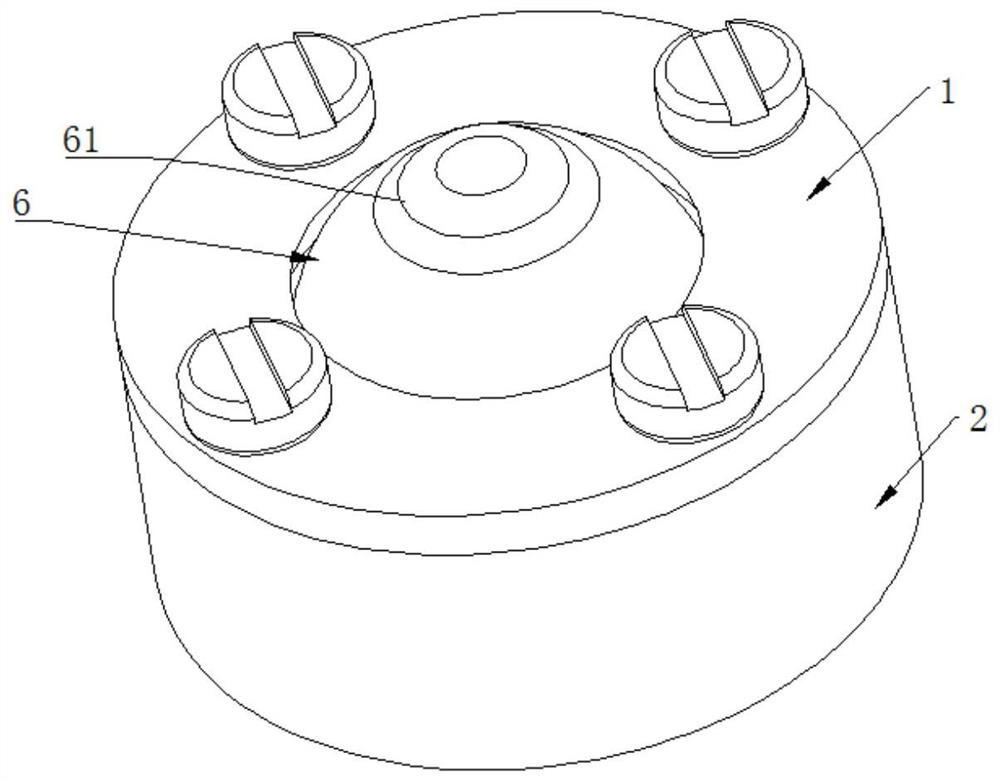
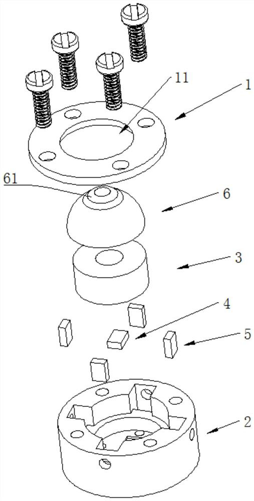
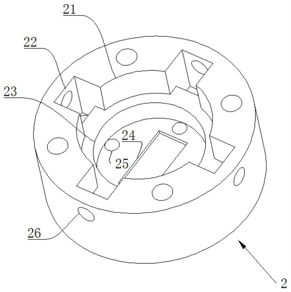
[0032] see Figure 1-4 , the present invention discloses a tactile sensor, comprising a bottom case 2 and a top cover 1 rigidly connected. The outer contour of the bottom shell 2 is cylindrical, and the top cover 1 is mounted on a circular plate, and a first through hole 11 is opened in the center of the top cover 1 . The bottom case 2 and the top cover 1 are connected by bolts, and the purpose is to take advantage of the advantages of easy disassembly of the bolted connections. Those skilled in the a...


PUM


Abstract

The invention belongs to the field of sensors, and particularly relates to a tactile sensor, which aims at solving the problems that the existing tactile sensor is easily interfered by an external environment and is not strong in robustness, and comprises a bottom shell and a top cover which are rigidly connected, a cavity is formed between the bottom shell and the top cover, and a first through hole is formed in the top cover; a light source, an elastic and light-transmitting elastic part and a photosensitive sensor are arranged in the cavity; the light source and the photosensitive sensor are respectively positioned on two opposite sides of the elastic part; a photosensitive area of the photosensitive sensor receives light penetrating through the elastic part; a rigid and lightproof touch component is arranged on the side, away from the bottom shell, of the elastic component, abuts against the bottom shell and the top cover and extends out of the first through hole; when the touch component extrudes the elastic component, the touch component partially shields the photosensitive area of the photosensitive sensor.

Description

technical field [0001] The invention relates to the field of sensors, in particular to a touch sensor. Background technique [0002] Tactile sensor is a biosensor technology that can obtain various information about contact characteristics, such as temperature, humidity, texture, sliding and other sensory information, and has a wide range of applications in medical, health, sports, entertainment, industrial and military fields prospect. In particular, the three-dimensional tactile sensor can detect the vertical, vertical and horizontal three-dimensional contact force of the space at the same time, and has the flexibility similar to human skin, so that it can better complete the hardness, roughness, material, etc. of objects in the external environment. Perception and manipulation of surface features. [0003] Existing three-dimensional flexible tactile sensors are mainly concentrated in three types: piezoresistive, capacitive and piezoelectric. The piezoresistive tactile ...

Claims


Application Information

Patent Timeline
IPC IPC(8): G01L1/24
CPCG01L1/24
Inventor 程龙侯增广谭民李正伟李厚成
Owner INST OF AUTOMATION CHINESE ACAD OF SCI
Features
  • R&D
  • Intellectual Property
  • Life Sciences
  • Materials
  • Tech Scout
  • Unparalleled Data Quality
  • Higher Quality Content
  • 60% Fewer Hallucinations
Learn More