Automatic commutation device detection device and method based on PWM converter

A technology for equipment detection and converters, applied in measuring devices, instruments, measuring electricity, etc., can solve the problems of endangering the safe operation of the system, users' safe electricity consumption, electric shocks for on-site operators, and expanding the scope of user power outages, etc., so as to modify the test parameters. Convenient and fast, improve safety factor, and friendly human-computer interaction

Inactive Publication Date: 2020-03-24
YUNNAN POWER GRID CO LTD LINCANG POWER SUPPLY BUREAU
View PDF13 Cites 0 Cited by
  • Summary
  • Abstract
  • Description
  • Claims
  • Application Information

AI Technical Summary

Problems solved by technology

However, due to the dispersion of users, the diversity of loads and the randomness of cut-in, almost all low-voltage distribution networks have three-phase unbalance problems
This three-phase unbalance problem will lead to line loss in the power grid and increase the copper loss and iron loss of the transformer, and even reduce the output of the transformer, which will affect the normal supply of electric energy and reduce the quality of electric energy, endangering the safe operation of the system and users. Safe use of electricity
[0003] In order to solve this problem, it is feasible to manually change the line to adjust the load, but it is neither safe nor economical. Therefore, low-voltage automatic commutation loa

Method used


Image

  • Automatic commutation device detection device and method based on PWM converter
  • Automatic commutation device detection device and method based on PWM converter
  • Automatic commutation device detection device and method based on PWM converter

Examples


Embodiment Construction

[0056] The present invention will be further described in detail below in conjunction with the examples.

[0057] Those skilled in the art will understand that the following examples are only for illustrating the present invention and should not be considered as limiting the scope of the present invention. If no specific technique or condition is indicated in the examples, it shall be carried out according to the technique or condition described in the literature in this field or according to the product specification. The materials or equipment used are not indicated by the manufacturer, and they are all conventional products that can be obtained through purchase.

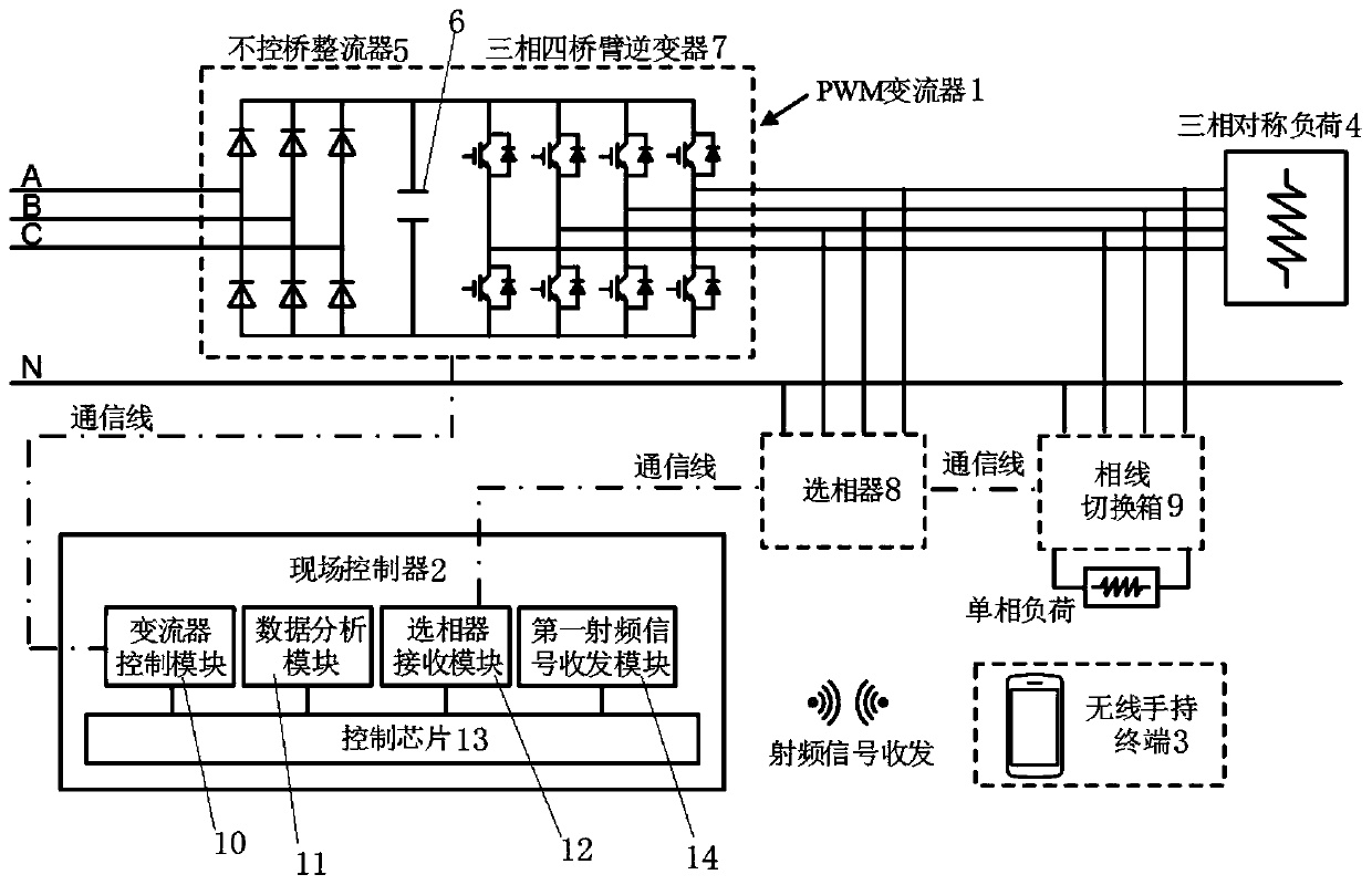
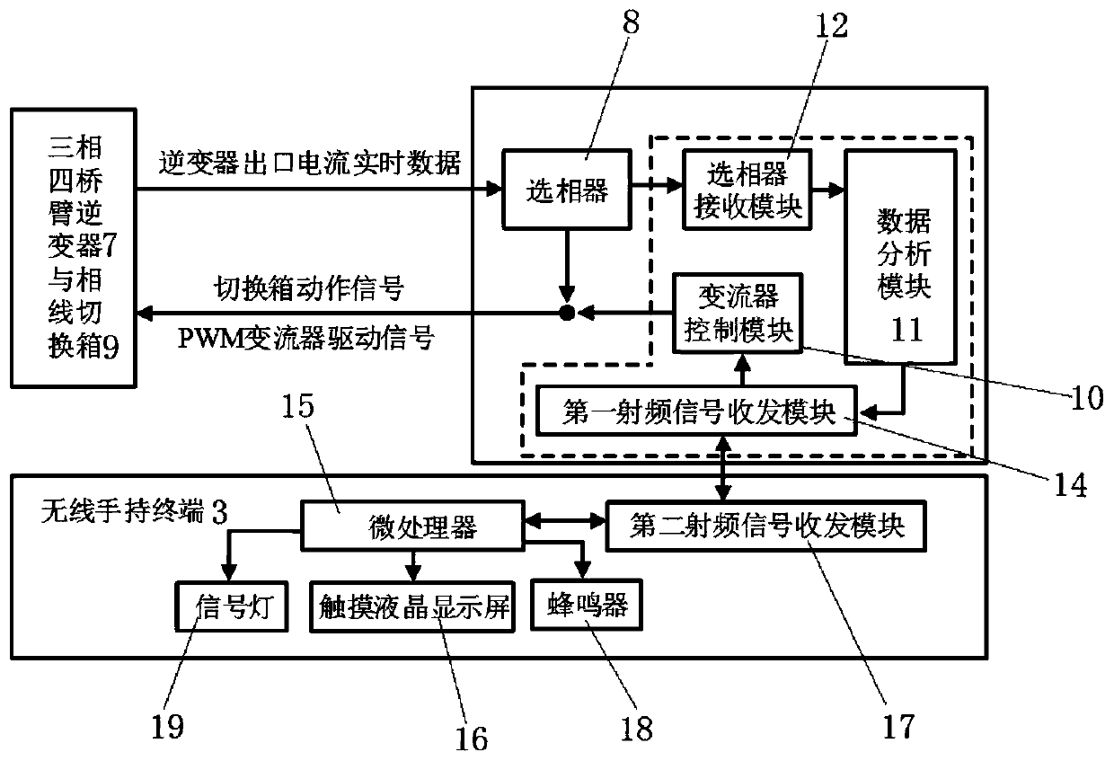
[0058] like Figure 1~2 As shown, a detection device for automatic phase change equipment based on PWM converters, the automatic phase change equipment includes a phase selector 8 and a phase line switching box 9, and the phase selector 8 and phase line switching box 9 are connected in parallel to three-phase fou...


PUM


Abstract

The invention relates to an automatic commutation device detection device and method based on a PWM converter, and belongs to the technical field of device detection. The detection device comprises the PWM converter, a field controller, a wireless handheld terminal and a three-phase symmetrical load. The field controller comprises a converter control module, a data analysis module, a phase selector receiving module, a control chip and a first radio frequency signal transceiving module, and the wireless hand-held terminal comprises a microprocessor, a touch liquid crystal display screen, a second radio frequency signal transmit-receive module and other structures. According to the automatic commutation device detection device and method based on the PWM converter, a detection way for the performance of a current low-voltage automatic phase-change device is provided, the situation that the current low-voltage automatic phase-change device is put in use on the premise that the performanceof the low-voltage automatic phase-change device is unknown is avoided, and further the loss caused by cutting off the power supply of the users after the device is used for the on-site test and maintenance is avoided, and the potential safety operation hidden dangers are avoided.

Description

technical field [0001] The invention belongs to the technical field of equipment detection, and in particular relates to a detection device and method for automatic phase-commutation equipment based on a PWM converter. Background technique [0002] At present, most of my country's low-voltage distribution network supplies power to users in a three-phase four-wire system through 10kV / 0.4kV transformers. However, due to the dispersion of users, the diversity of loads and the randomness of cut-in, almost all low-voltage distribution networks have three-phase unbalance problems. This three-phase unbalance problem will lead to line loss in the power grid and increase the copper loss and iron loss of the transformer, and even reduce the output of the transformer, which will affect the normal supply of electric energy and reduce the quality of electric energy, endangering the safe operation of the system and users. safe electricity use. [0003] In order to solve this problem, it...

Claims


Application Information

Patent Timeline
IPC IPC(8): G01R31/00
CPCG01R31/00
Inventor 石定中罗玉珠黄继盛高景林杨绍露
Owner YUNNAN POWER GRID CO LTD LINCANG POWER SUPPLY BUREAU
Why Eureka
Try Eureka