Optical imaging lens
An optical imaging lens and imaging technology, applied in the field of optical imaging, can solve problems such as unfavorable thinning of mobile phones and digital cameras, and achieve the effect of a large field of view.
- Summary
- Abstract
- Description
- Claims
- Application Information
AI Technical Summary
Problems solved by technology
Method used
Image

Examples
Embodiment Construction
[0074] Before starting to describe the present invention in detail, first clearly represent the symbolic explanation in the accompanying drawings:
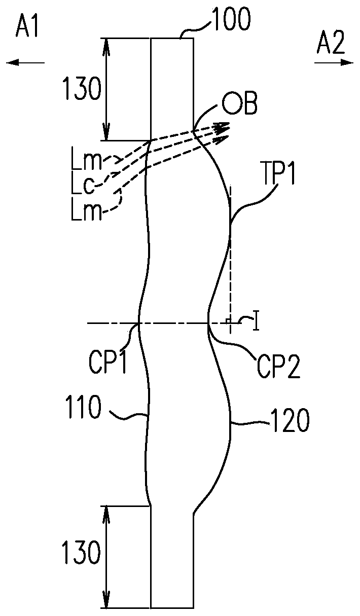
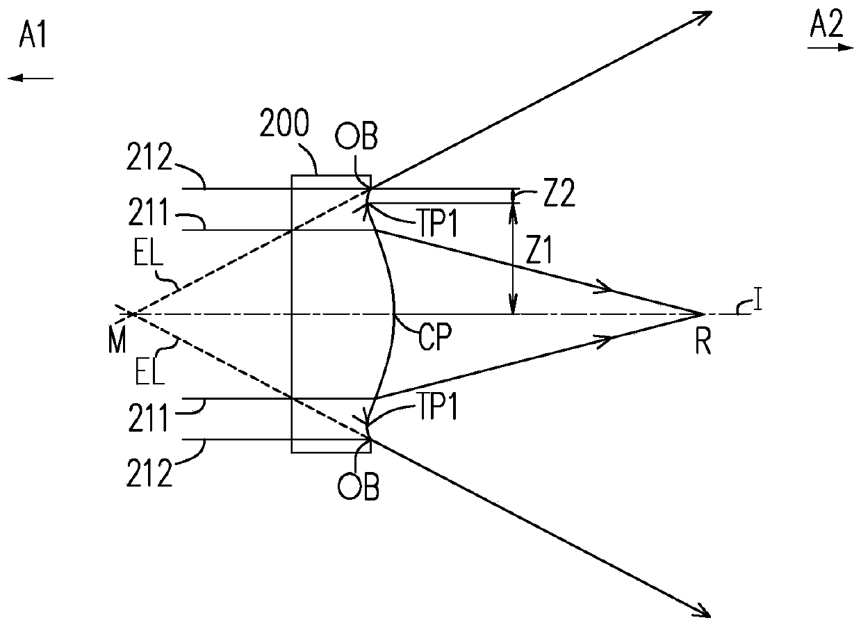
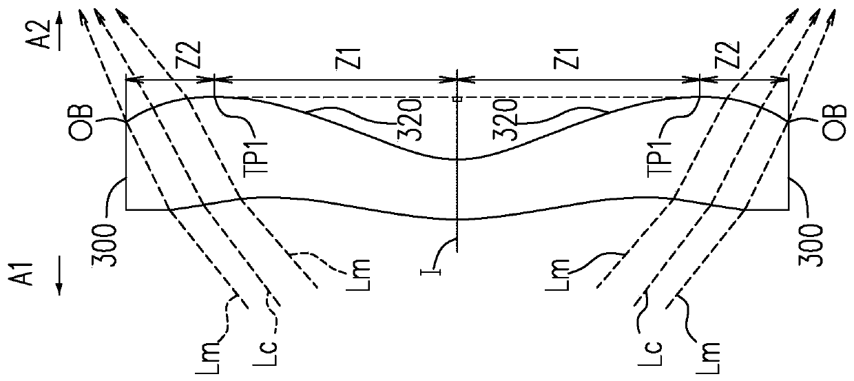
[0075] 0: aperture; 1: first lens; 2: second lens; 3: third lens; 4: fourth lens; 5: fifth lens; 9: optical filter; 10: optical imaging lens; 15, 25, 35, 45, 55, 95, 110, 410, 510: object side; 16, 26, 36, 46, 56, 96, 120, 320: image side; 99: image plane; 100, 200, 300, 400, 500 : lens; 130: assembly part; 151, 161, 251, 261, 351, 361, 451, 461, 551, 561, Z1: optical axis area; 153, 163, 253, 263, 353, 363, 453, 463, 553, 563, Z2: circumference area; 211, 212: parallel rays; A1: object side; A2: image side; CP: center point; CP1: first center point; CP2: second center point; EL: extension line; I: optical axis; Lm: marginal ray; Lc: chief ray; M, R: intersection point; OB: optical boundary; TP1: first transition point; TP2: second transition point Z3: relay area.
[0076] The terms used in this specification and claims: optical...
PUM
 Abstract
Description
Claims
Application Information
 - R&D
- Intellectual Property
- Life Sciences
- Materials
- Tech Scout
- Unparalleled Data Quality
- Higher Quality Content
- 60% Fewer Hallucinations
Browse by: Latest US Patents, China's latest patents, Technical Efficacy Thesaurus, Application Domain, Technology Topic, Popular Technical Reports.
© 2025 PatSnap. All rights reserved.Legal|Privacy policy|Modern Slavery Act Transparency Statement|Sitemap|About US| Contact US: help@patsnap.com