

Method for fixing LED chip on back plate
A LED chip and backplane technology, applied in the field of LED chip fixing, to achieve the effect of simple process and easy industrial mass production
- Summary
- Abstract
- Description
- Claims
- Application Information
AI Technical Summary
Problems solved by technology
Method used
Image

Examples
Embodiment 1
[0043] Embodiment 1 Method A for fixing LED chips to the backplane
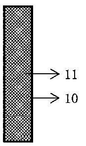
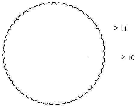
[0044] A, such as figure 1 , image 3 As shown, select a wire rod with concave points on the surface, the hole diameter of the concave point is about 1 / 6 of the bottom side length of the LED chip, and the relative bump is about 1 / 6 of the bottom side length of the LED chip.
[0045] B. Take a transparent glass substrate and use a wire rod to roll on the surface A of the glass substrate to form a grid-like colloid. The thickness of the colloid is controlled at about 5.2µm, such as Figure 4 shown.
[0046] C. Fix the LED chip on the grid-like colloid on the A side of the glass substrate. The distance between the LED chips is equal to the gap size of the fixed LED chip position on the backplane, and make the P\N electrode position of the chip and the power ± contact on the backplane corresponding to the location, such as Figure 5 shown.
[0047] D. The glass substrate with the LED chip fixed is superimpos...
Embodiment 2
[0051] Embodiment 2 Method B for fixing LED chips to the backplane
[0052] A, Choose double-sided adhesive with a viscosity of about 20g / m / s, and control the thickness of the glue at about 5.2µm.
[0053] B, the double-sided tape is pasted on the A side of the glass substrate.
[0054] C. Fix the LED chip on the double-sided adhesive on the A side of the glass substrate. The distance between the LED chips is equal to the gap size of the fixed LED chip position on the backplane, and the P\N electrode position of the chip is the same as the power ± contact position on the backplane. correspond.
[0055] D. The glass substrate with the LED chip fixed is superimposed on the backplane, so that the P\N electrodes of the LED chip are bonded to the ± contact points on the backplane, such as Figure 7 shown.
[0056] E, the laser penetrates the glass substrate from the B side of the glass substrate, so that the P\N electrodes of the LED chip and the ± contact points on the backplan...
Embodiment 3
[0059] Example 3 Yield experiment of Micro LED chips fixed on the backplane
[0060] Take backplanes, Micro LED chips, and glass substrates with the same specifications, and divide them into four groups at random, namely, Group A, Group B, Group C, and Group D. Each group has 20 backplanes.
[0061] Group A: On the surface A of the glass substrate, the entire surface is coated with UV glue. The adhesiveness is controlled at about 4g / m / s, and the thickness of the glue is about 10µm. Micro LED chips are fixed on the glue on the surface A of the glass substrate. The distance between them is equal to the gap size of the fixed LED chip position on the backplane, and the P\N electrode position of the chip corresponds to the power ± contact position on the backplane. The glass substrate on which the Micro LED chip is fixed is superimposed on the backplane, so that the P\N electrodes of the Micro LED chip are bonded to the ± contact points on the backplane, and the laser penetrates th...
PUM
| Property | Measurement | Unit |
|---|---|---|
| Melting point | aaaaa | aaaaa |
Abstract
Description
Claims
Application Information