A Low Phase Noise Microwave Frequency Comb Generator with Adjustable Comb Distance

A technology with low phase noise and microwave frequency, applied in the direction of solid-state lasers, etc., can solve the problems of fixed comb distance and large phase noise, and achieve the effect of increasing frequency components, large frequency multiplication factor, and increasing the number of photoelectric oscillation loops

Active Publication Date: 2021-01-15
TIANJIN UNIV
View PDF6 Cites 0 Cited by
  • Summary
  • Abstract
  • Description
  • Claims
  • Application Information

AI Technical Summary

Problems solved by technology

[0004] Aiming at the prior art, the present invention provides a microwave frequency comb generator with adjustable comb distance and low phase noise, which solves the problem of fixed comb distance and large phase noise in the existing microwave frequency comb generation system, and at the same time have a fixed phase relationship between

Method used


Image

  • A Low Phase Noise Microwave Frequency Comb Generator with Adjustable Comb Distance

Examples


Embodiment

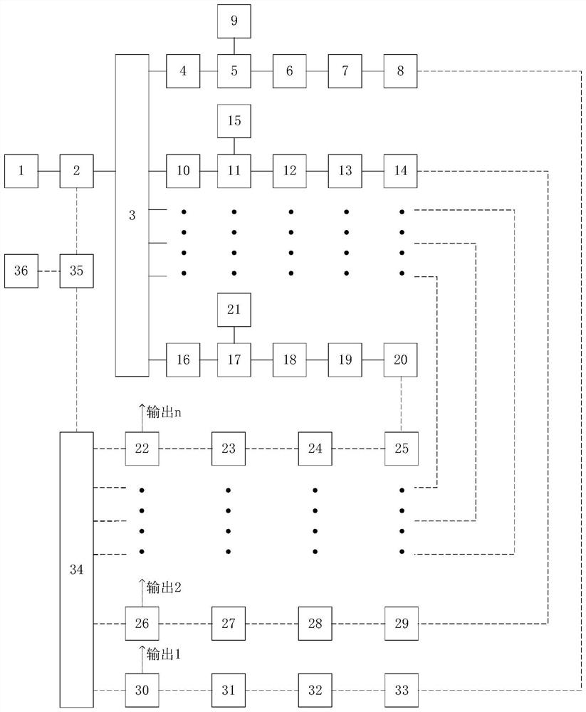
[0021] Example: using figure 1 The shown microwave frequency comb generator generates a low phase noise microwave frequency comb with adjustable comb distance. The specific process is as follows:

[0022] Step 1: adjust the bias voltage of the intensity modulator 2, so that the microwave signal generated by the microwave source 36 modulates the continuous optical signal generated by the laser 1 to form sidebands of each order of the optical signal, and adjust the three polarization controllers 4, 10 , 16; match the corresponding DFB laser.

[0023] Step 2: Adjust the parameters of the three DFB lasers 9, 15, and 21 drive units, inject and lock the sidebands of the corresponding optical signals to increase their optical power, and pass through three optical delay lines 6, 12, 18 and three respectively After the long optical fibers 7, 13, 19, they enter three corresponding photodetectors 8, 14, 20 to form respective beat frequency signals.

[0024] Step 3: The generated beat f...


PUM


Abstract

The invention discloses a low-phase noise microwave frequency comb generator with an adjustable comb pitch. A continuous light signal generated by a laser enters an intensity modulator, and a modulation signal generated after modulation of a microwave source enters the intensity modulator to modulate the continuous light generated by the laser and then divides the continuous light into N paths oflight; optical injection locking is performed, namely different harmonic components are locked by using N DFB lasers, and the harmonic components enter corresponding photoelectric detectors respectively through an optical delay line and a long optical fiber in sequence to generate different beat frequency signals so as to generate frequency doubling microwave signals with different multiples; andeach path of microwave signal is fed back to the light intensity modulator after being amplified and filtered respectively, so that N mutually independent injection locking photoelectric oscillation loops are formed, and finally, the output of the microwave frequency comb is realized. All outputs have a fixed phase relationship, and the phase noise is very low. And the output of multi-frequency-point signals with unequal frequency intervals can be realized by adjusting each path of DFB laser.

Description

technical field [0001] The invention relates to a microwave frequency comb, in particular to a microwave frequency comb generator with adjustable comb distance and low phase noise. Background technique [0002] The microwave frequency comb is composed of a series of discrete microwave signals with a certain interval, and can output microwave signals with multiple frequency points in one frequency band. The microwave frequency comb has the advantages of large number of spectral lines, wide frequency range, and high precision of spectral line spacing. It has a wide range of applications in communication, military, medical and other aspects, and has attracted extensive attention from researchers at home and abroad. [0003] At present, the generation methods of microwave frequency combs mainly include electrical and optical methods. Although the traditional electrical method can generate frequency combs with a bandwidth of more than ten GHz, the comb pitch of the generated freq...

Claims


Application Information

Patent Timeline
Patent Type & Authority Patents(China)
IPC IPC(8): H01S1/02
CPCH01S1/02
Inventor 王菊郭学鑫于晋龙于洋马闯
Owner TIANJIN UNIV
Why Eureka
Try Eureka