Straw row-returning shallow-pressing covering strip tiller

A technology of covering strips and cultivating machines, which is applied in the field of agricultural machinery, can solve the problems of affecting work efficiency, inability to achieve effective suppression of straw, uneven distribution of straw, etc., and achieve the effect of improving work efficiency

Pending Publication Date: 2020-03-27
NORTHEAST INST OF GEOGRAPHY & AGRIECOLOGY C A S
View PDF1 Cites 4 Cited by
  • Summary
  • Abstract
  • Description
  • Claims
  • Application Information

AI Technical Summary

Problems solved by technology

However, there is no matching equipment for straw farming and shallow pressure mulching strip farming.
[0005] At present, the existing strip rotary tillers usually use the transmission mode of the side box of the rotary tiller, which can effectively avoid the situation of missing tillage of the strip rotary belt, but the uneven distribution of straw caused by the side box dragging pile seriously restricts this technology. extensive promotion of
The front structure of the straw processing mechanism, due to the unevenness of the land, often leads to the suspension of the tractor, which affects the effect of the straw return, resulting in the accumulation of straw
Narrow rubber wheels can play a good role in limiting the depth, but they cannot achieve the problem of effective suppression of straw. Due to the strong wind in the spring planting season in Northeast my country, the returned straw is often blown away due to the problem of strong wind, resulting in straw The distribution is uneven, which affects the emergence of crops, and it is difficult to achieve the effect of suppression and moisture conservation with single-roller suppression
The current strip rotary tiller cannot meet the technical requirements of the straw returning shallow pressure covering strip tillage
[0006] The existing authorization announcement number of "A Front-mounted Corn Protective Tillage Straw Returning Machine": CN 207720650U, from figure 1 It can be seen from the figure that the spring tooth 18 is installed on the finger plate 17, and the inner diameter of the finger plate 17 and the spring tooth 18 are hollowed out. When working, the straw is easy to enter from the hollowed out place and wrap around the finger plate 17 and the spring tooth 18. As a result, the straw cannot be evenly covered, and even the finger plate 17 cannot be rotated, thereby affecting work efficiency

Method used


Image

  • Straw row-returning shallow-pressing covering strip tiller
  • Straw row-returning shallow-pressing covering strip tiller
  • Straw row-returning shallow-pressing covering strip tiller

Examples


specific Embodiment approach 1

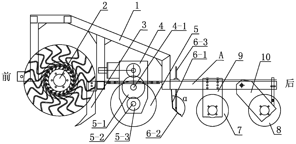
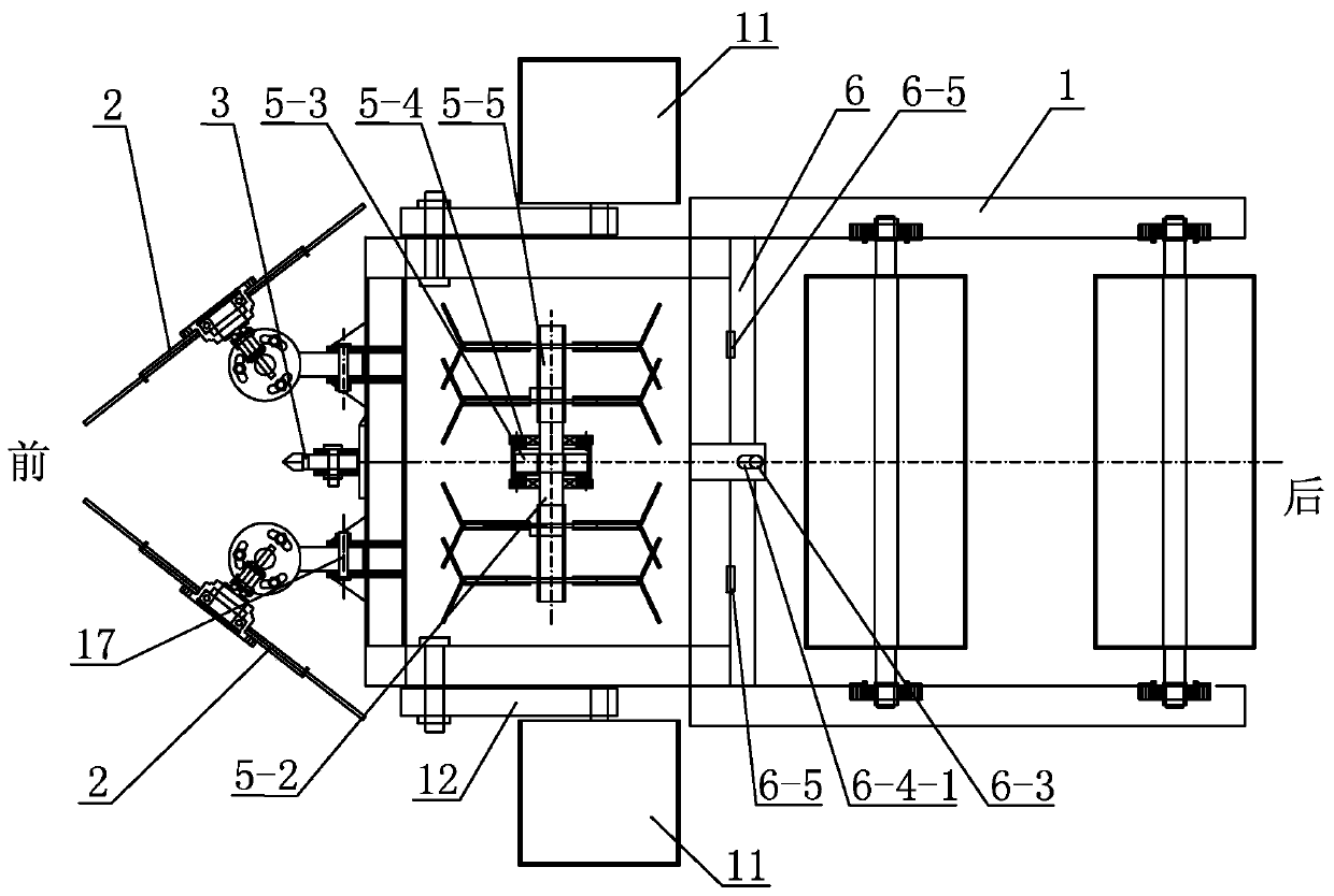
[0036] Specific implementation mode one: combine figure 1 and figure 2 Describe this embodiment, this embodiment includes two rows of straw returning machine A, two rows of straw returning machine A includes main frame 1, subsoiling shovel 3, power transmission mechanism 4, rotary tillage mechanism 5, soil retaining plate 6, limiter Deep pressure roller 7, auxiliary pressure roller 8, two straw cleaning mechanisms 2, two fixed plates 9, two movable plates 10, two pressure wheels 11, two linkage rods 12, two support rods 13, two support rods plate 14, two nuts 15, two springs 16 and two connecting pins 17;

[0037] The subsoiler shovel 3, the rotary tillage mechanism 5, the retaining plate 6, the depth-limiting pressure roller 7 and the auxiliary pressure roller 8 are arranged under the main frame 1 from front to back, and two straw cleaning mechanisms 2 are arranged at the front end of the main frame 1 , the two straw cleaning mechanisms 2 are arranged symmetrically with re...

specific Embodiment approach 2

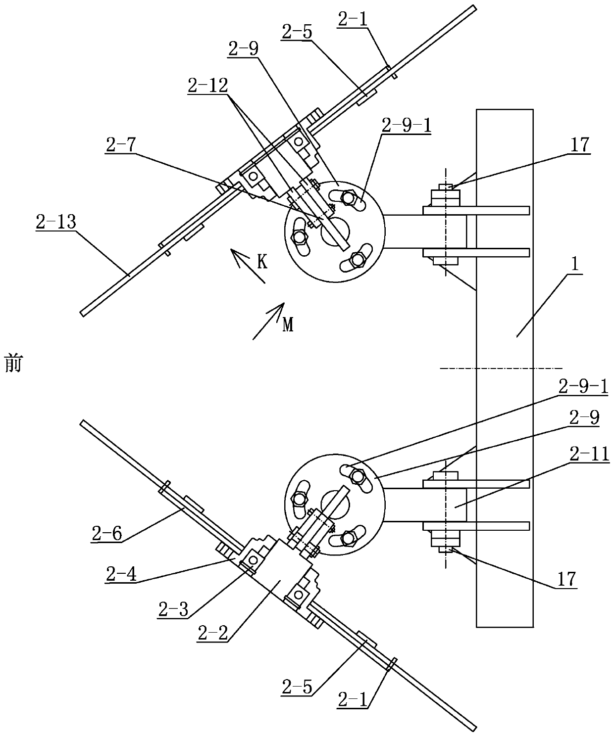
[0039] Specific implementation mode two: combination Figure 3 ~ Figure 7 To illustrate this embodiment, the straw cleaning mechanism 2 of this embodiment includes an outer ring 2-1, a fixed shaft 2-2, a bearing 2-3, a bearing sleeve 2-4, an inner circular baffle 2-5, and an outer circular baffle 2 -6, vertical angle adjustment plate 2-7, pin shaft 2-8, horizontal angle adjustment plate 2-9, fixed plate 2-10, connecting rod 2-11, two splints 2-12 and several elastic teeth 2 -13;

[0040] Several spring tooth holes 2-1-1 are evenly distributed along the circumference of the outer ring 2-1, and each spring tooth hole 2-1-1 is provided with a spring tooth 2-13, and several spring teeth 2-13 The outer end forms the same diameter, and the inner ends of several spring teeth 2-13 form the same diameter, and the several spring teeth 2-13 and the outer ring 2-1 form a spring tooth disc, and the bearing 2-3 and the bearing sleeve 2-4 are formed from the inside Outwardly and sequential...

specific Embodiment approach 3

[0041] Specific implementation mode three: combination Figure 5 and Figure 7 To describe this embodiment, an annular gap S is provided between the outer circular baffle plate 2-6 and the outer ring 2-1 of this embodiment, and the annular gap S is 10 mm to 20 mm. The annular gap S makes the elastic teeth 2-13 more elastic, and can better bounce off the straw. Other components and connections are the same as those in the second embodiment.


PUM


Abstract

The invention discloses a straw row-returning shallow-pressing covering strip tiller. The straw row-returning shallow-pressing covering strip tiller can achieve the operations of straw cleaning, uniform row returning, strip rotary tillage, row-returning straw shallow-pressing fixing, rotary tillage strip pressing, straw row-returning strip pressing and the like at a time, and therefore, the agricultural requirements of straw row-returning shallow-pressing covering strip tillage are met. An adjustable soil blocking plate can achieve the number of soil splashes in strip rotary tillage, and therefore, the straw shallow-pressing fixing condition can be adjusted according to the specific soil and wind power condition. A main component row-returning machine A comprises a main rack, a subsoiler,a power transmission mechanism, a rotary tillage mechanism, the soil blocking plate, a depth limiting pressing roller, an auxiliary pressing roller, two straw cleaning mechanisms, two fixed plates, two movable plates, two pressing wheels, two linkage rods, two supporting plates, two nuts, two springs and two connecting pins. The straw row-returning shallow-pressing covering strip tiller can complete the operations of straw cleaning, deep scarification, rotary tillage, straw shallow-pressing covering, soil pressing and straw pressing at a time.

Description

technical field [0001] The invention relates to the field of agricultural machinery, in particular to a strip cultivator for shallow pressing and covering of straw. Background technique [0002] Straw returning to the field is already the most critical technical link in agricultural planting. Modern agricultural technology and planting technology are inseparable from the use of straw. Conservation tillage technology includes straw mulching. Both the national level and ordinary farmers are concerned about the issue of straw. Mulching is the most acceptable method of straw returning to the field by farmers. Straw returns to cover and fertilize the soil, which solves the whereabouts of straw and prevents straw burning. [0003] The arable land area in Northeast China is 450 million mu, accounting for 22.2% of the total arable land area in the country, and the grain commodity rate is over 60%, making it the country's largest commercial grain base. However, the continuous soil ...

Claims


Application Information

Patent Timeline
IPC IPC(8): A01B49/02
CPCA01B49/02
Inventor 敖曼关义新马驷骢李波杨青云苗永强杨青奎谢宏图
Owner NORTHEAST INST OF GEOGRAPHY & AGRIECOLOGY C A S
Why Eureka
Try Eureka