Dust collector

A technology for vacuum cleaners and suction heads, applied in the direction of vacuum cleaners, suction filters, suction nozzles, etc., can solve the problems of small air suction, high temperature, high cost, etc., and achieve the effects of not easy to wear, long service life, and low cost

Pending Publication Date: 2020-03-27
刘慕华
View PDF6 Cites 0 Cited by
  • Summary
  • Abstract
  • Description
  • Claims
  • Application Information

AI Technical Summary

Problems solved by technology

However, this type of motor is generally composed of a casing, permanent magnet steel, carbon brushes, rotors and rotor windings. During operation, high-speed friction will be generated between the carbon brushes and the commutator while the rotor windings are constantly switching currents. Sparks are easily generated between the carbon brush and the commutator. If the speed is too high, it will cause serious wear between the carbon brush and the commutator, which will affect the product life and even burn out quickly
If a conventional brushless motor is used as a vacuum cleaner motor, at high speeds, its bearings will lose energy and increase in temperature due to mechanical friction, resulting in damage to the bearings, making maintenance and replacement more frequent, making the existing brushless motors unbearable The speed is too high, so that the maximum speed can only reach about 80,000RPM, and the high performance of the ultra-high speed of 150,000RPM cannot be achieved, and the air suction is small
Motors using magnetic levitation bearings have problems with high costs, which in turn increases the cost of vacuum cleaners

Method used


Image

  • Dust collector
  • Dust collector
  • Dust collector

Examples


Embodiment 1

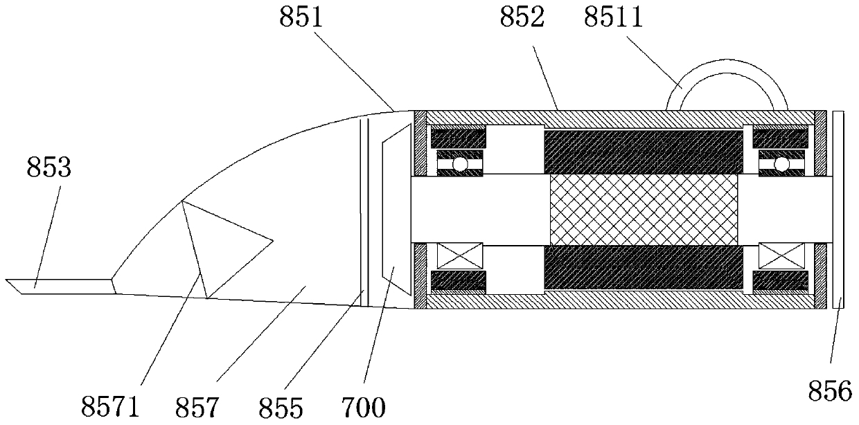
[0054] see figure 1 , a vacuum cleaner using a parallel bearing motor, including a housing 851, a motor 852 and a suction head 853; the two ends of the housing 851 are respectively connected to the motor 852 and the suction head 853, the output end of the motor 852 is connected to the turbine 700, and the filter device 8585 is arranged on the housing Inside 851, the shell 851 is divided into two parts, the part close to the motor 852 accommodates the turbine 700, the part close to the dust suction head 853 is the dust collection chamber 857, the input end of the motor 852 is connected to the circuit board 856, and the circuit board 856 is connected to the power supply for To control the start and stop of the motor 852, a handle 8511 is provided on the housing 851, and a funnel-shaped anti-reflux cover 8571 is arranged in the dust collection chamber 857. Dust falls out from the suction head 853.

Embodiment 2

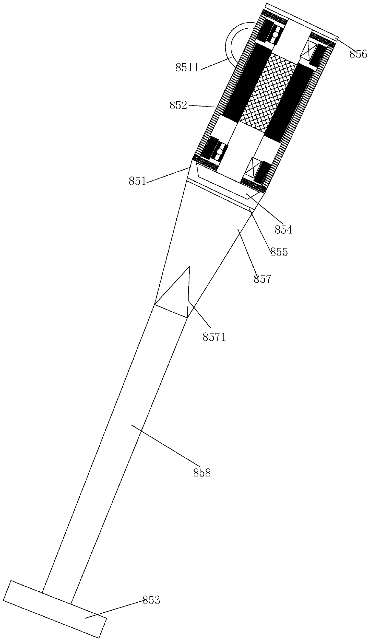
[0056] see figure 2 , this embodiment of the vacuum cleaner is based on the first embodiment of the vacuum cleaner, and a handle 858 is provided between the casing 851 and the dust suction head 853 to extend the length of the vacuum cleaner.

Embodiment 3

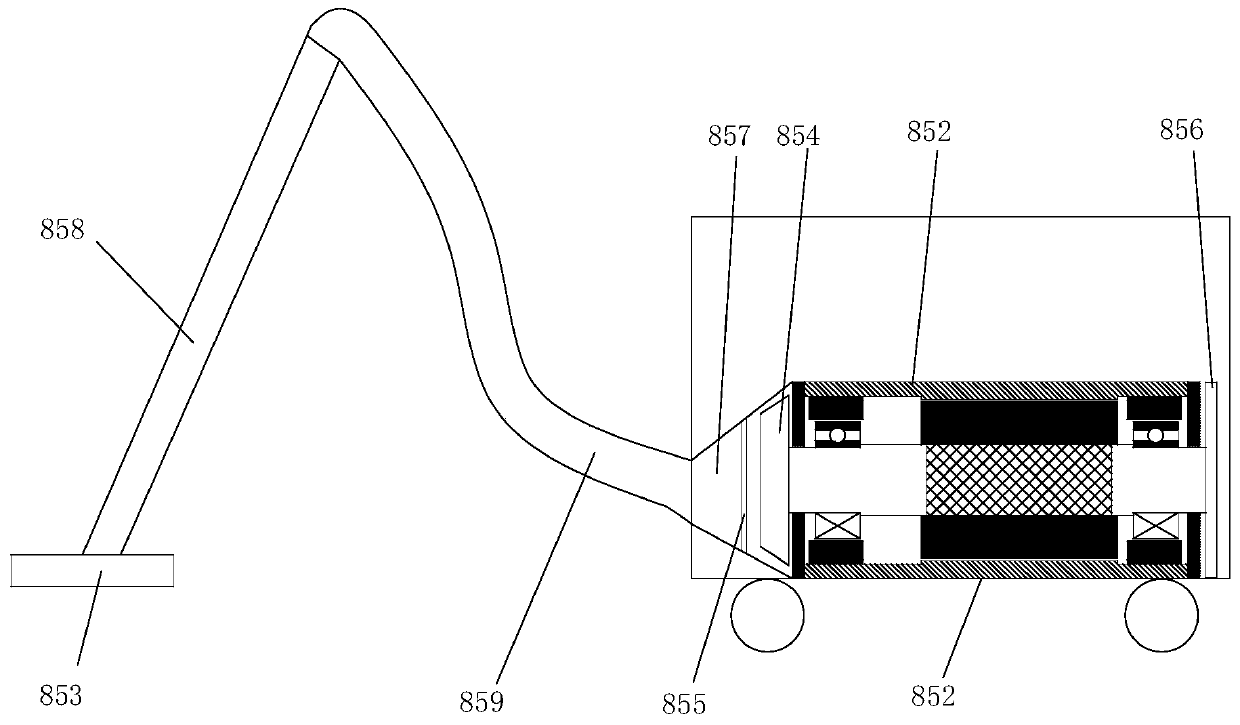
[0058] see image 3 , this embodiment of the vacuum cleaner is based on the second embodiment of the vacuum cleaner, and a hose 859 is provided between the handle 858 and the casing 851 to increase the dust collection range of the dust suction head 853 . In addition, the motor 852 is covered with a box 61 , and the bottom of the box 61 is provided with a roller 62 .

[0059] The dust collection process of the above-mentioned embodiment is: after the power is turned on, the turbine 700 generates a relatively high suction force at a high speed, and under the action of the suction force, the air is discharged at a high speed, and an instantaneous vacuum is generated inside the dust suction head 853, forming a negative pressure difference with the external atmospheric pressure , under the action of this pressure difference, the air containing dust can be sucked. Dust and other sundries enter the dust collection chamber 857 through the dust suction head, and the dust and other sun...


PUM


Abstract

The invention discloses a dust collector which comprises a shell and a dust collection head. Two ends of the shell are respectively connected with a motor and the dust collection head; the output endof the motor is connected with a turbine. The motor comprises a rotor system and a motor assembly, the rotor system comprises a rotating shaft, and a pair of parallel bearings is arranged on the rotating shaft and comprises a rotating shaft bearing and a stator bearing; the rotating shaft bearing is a contact type bearing, sleeves the rotating shaft and is in close fit with the rotating shaft; thestator bearing is a non-contact bearing, the stator bearing sleeves the rotating shaft bearing, a gap is reserved between the inner wall of the stator bearing and the outer wall of the rotating shaftbearing, and the stator bearing is fixed on the stator; the motor assembly comprises a stator magnetic pole and a coil which sleeve the rotating shaft, and a magnetic core is arranged on a shaft section, located in the stator magnetic pole and the coil, of the rotating shaft; a filtering device is arranged in the shell and divides the shell into two parts, the part close to the parallel bearing motor contains the turbine, and the part close to the dust collection head is a dust collection cavity. The dust collector is large in air suction amount, cleaner in sweeping and low in cost.

Description

technical field [0001] The invention relates to the technical field of vacuum cleaners, in particular to a vacuum cleaner. Background technique [0002] Vacuum cleaner motors are required to have the characteristics of small size and high speed. At present, most of the main vacuum cleaner products at home and abroad use series motors or brushed DC motors. In order to achieve miniaturization and weight reduction while satisfying greater suction effects, it is often necessary to increase the speed. However, this type of motor is generally composed of a casing, permanent magnet steel, carbon brushes, rotors and rotor windings. During operation, high-speed friction will be generated between the carbon brushes and the commutator while the rotor windings are constantly switching currents. As a result, sparks are easily generated between the carbon brush and the commutator. If the speed is too high, it will cause serious wear between the carbon brush and the commutator, which will...

Claims


Application Information

Patent Timeline
Patent Type & Authority Applications(China)
IPC IPC(8): A47L5/24A47L9/02A47L9/10A47L9/00A47L9/28
CPCA47L5/24A47L9/02A47L9/10A47L9/00A47L9/28
Inventor 刘慕华
Owner 刘慕华
Why Eureka
Try Eureka