
Crushing, drying and screening device for chemical materials

A screening device and chemical technology, applied in drying, drying machine, drying gas layout and other directions, can solve the problems affecting the average particle size of materials, the impact of material quality, and the scattering of dust, and achieve good results, safety protection, and no pollution. The effect of easy dust pollution

Inactive Publication Date: 2020-03-27
杨银龙
View PDF9 Cites 4 Cited by
  • Summary
  • Abstract
  • Description
  • Claims
  • Application Information

AI Technical Summary

Problems solved by technology

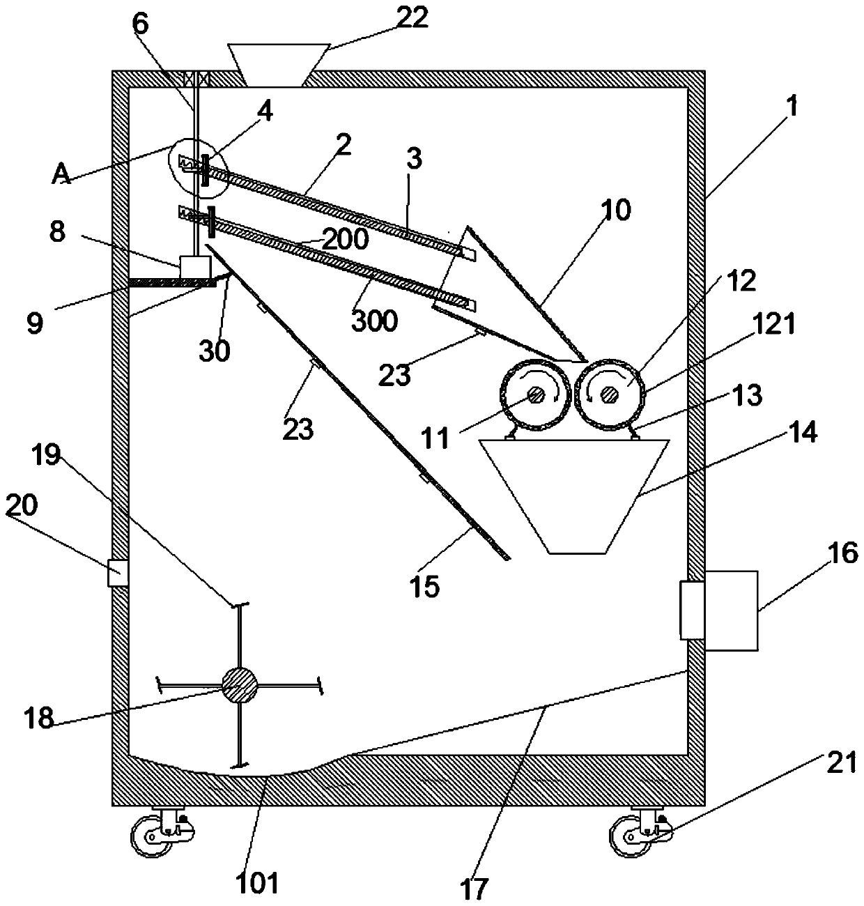
[0003] In addition, as human beings attach importance to environmental protection, improving the environmental protection measures of the dryer to reduce the leakage of dust and exhaust gas is a direction that needs in-depth research. In the process of dust drying, it is inevitable that a lot of dust will be scattered around. If the dust There are some larger particles in it, which will affect the overall average particle size of the material, so that the quality of the material is affected, and the existing powder material transmission and drying equipment will have relatively large dust pollution. Auxiliary equipment to continue screening and crushing; therefore, those skilled in the art provide a crushing, drying, and screening device for chemical materials to solve the problems raised in the above-mentioned background technology

Method used


Image

  • Crushing, drying and screening device for chemical materials
  • Crushing, drying and screening device for chemical materials
  • Crushing, drying and screening device for chemical materials

Examples


Embodiment Construction

[0022] The following will clearly and completely describe the technical solutions in the embodiments of the present invention with reference to the accompanying drawings in the embodiments of the present invention. Obviously, the described embodiments are only some, not all, embodiments of the present invention. Based on the embodiments of the present invention, all other embodiments obtained by persons of ordinary skill in the art without making creative efforts belong to the protection scope of the present invention.

[0023] In describing the present invention, it should be understood that the terms "center", "longitudinal", "transverse", "length", "width", "thickness", "upper", "lower", "front", " Back", "Left", "Right", "Vertical", "Horizontal", "Top", "Bottom", "Inner", "Outer", "Clockwise", "Counterclockwise", "Axial", The orientation or positional relationship indicated by "radial", "circumferential", etc. is based on the orientation or positional relationship shown in...


PUM


Abstract

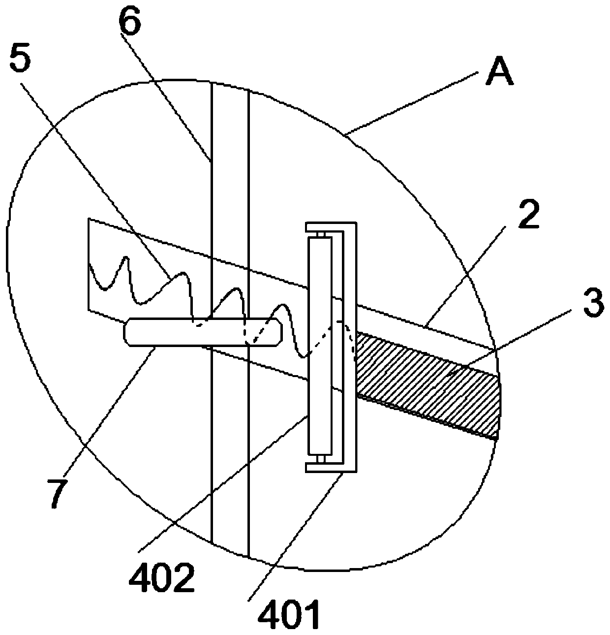
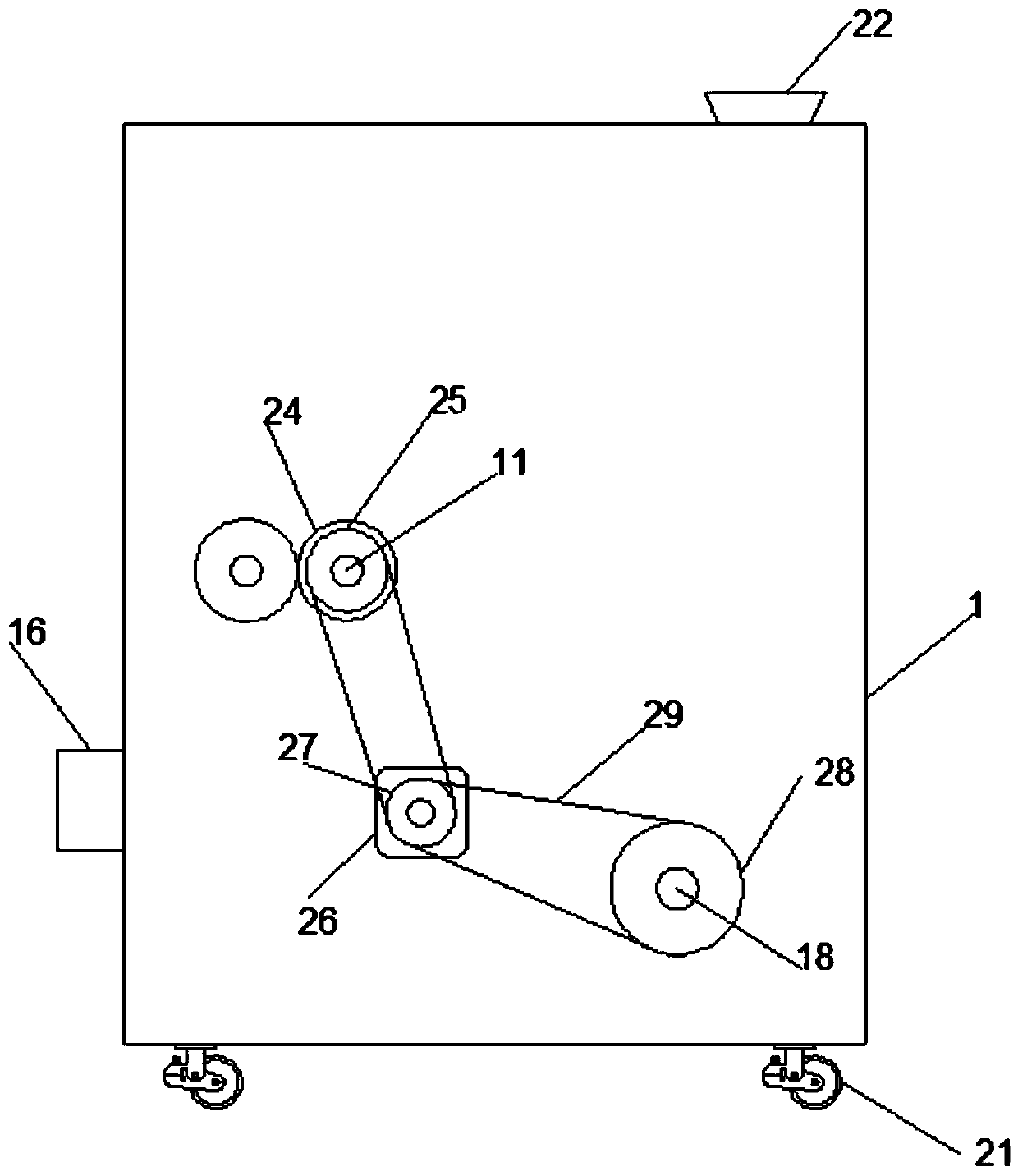
The invention discloses a crushing, drying and screening device for chemical materials. The device comprises a box body, a first screening plate, a second screening plate, a crushing roller and an airheater, wherein a first sliding groove and a second sliding groove are formed in each of the front and back inner walls of the left upper part of an inner cavity of the box body. According to the device, chemical raw material particles with the particle diameter meeting the requirements are screened by the first screening plate and the second screening plate and fall onto a sliding plate, and chemical raw material particles with the larger particle diameter not meeting the requirements are screened out and crushed by the crushing roller, so that the particle diameter of the chemical raw material particles meets the requirements; and then, when the chemical raw materials with the particle diameter meeting the requirements fall and are blown into an arc-shaped groove in the left side of thebottom of the inner cavity of the box body through the air heater, then a stirring shaft drives stirring blades to rotate to stir the chemical raw materials in the arc-shaped groove, meanwhile, hot air is blown out of the air heater as well to dry the chemical raw materials stirred by the stirring blades, the drying is rapid, the effect is good, the dried chemical raw material particles are blownout from a discharging opening, all the work is performed in the inner cavity of the box body, and waste and flying dust pollution are avoided.

Description

technical field [0001] The invention relates to the technical field of chemical machinery, in particular to a crushing, drying and screening device for chemical materials. Background technique [0002] The future development of the dryer will be based on the in-depth study of the drying mechanism and drying characteristics of materials, and mastering the optimal operating conditions for different materials, developing and improving the dryer, high economy, and improving the adaptability to raw materials and product quality. At the same time, further research and development of new types of dryers with high efficiency and special requirements, such as combined dryers, microwave dryers and far-infrared dryers, etc. The development of dryers should also pay attention to energy saving and comprehensive utilization of energy. Such as adopting various combined heating methods, transplanting heat pump and heat pipe technology, developing solar dryers, etc., and developing automatic...

Claims


Application Information

Patent Timeline
IPC IPC(8): B02C4/02B02C4/28B02C4/30B02C4/40B02C4/42B02C21/02B02C23/08B02C23/20B07B1/28B07B1/42B07B1/46F26B25/04F26B21/00B08B17/02B08B15/02
CPCB02C4/02B02C4/28B02C4/30B02C4/40B02C4/42B02C21/02B02C23/08B02C23/20B07B1/28B07B1/42B07B1/46B07B2201/04B08B15/02B08B17/02F26B21/004F26B25/04
Inventor 杨银龙
Owner 杨银龙
Learn More