Clutch driven disc heat treatment machining tool

A clutch and tooling technology, applied in heat treatment furnaces, heat treatment equipment, metal processing equipment, etc., can solve the problems of poor flatness of finished products, difficulty in leveling, difficult leveling, etc., to reduce high temperature leveling process, good quenching effect, The effect of ensuring the leveling accuracy

Pending Publication Date: 2020-03-27
CHANGCHUN YIDONG CLUTCH
View PDF0 Cites 0 Cited by
  • Summary
  • Abstract
  • Description
  • Claims
  • Application Information

AI Technical Summary

Problems solved by technology

[0002] The driven disc in the automobile clutch is a key part of the entire clutch, which directly affects the performance of the clutch. The driven disc is a thin-walled large-size part. During the production process, it is produced by quenching after carbonitriding and high-temperature leveling. Yes, the conditions are very harsh during use, and can only be used after heat treatment. When the driven disc is subjected to the joint action of tissue stress and thermal stress after heat treatment, the deformation of the parts is relatively large, and it needs to be leveled to be practical. The traditional leveling uses heating The flat mold uses high temperature and high pressure conditions to level the parts. The disadvantage is that the position of the parts after leveling under the high temperature and high pressure conditions is easy to deteriorate, and it is difficult to level when the deformation of the parts is large, resulting in waste products.
[0003] When using traditional production, the leveling process has the following defects: a high temperature of 350 degrees is required, and the processing cycle of each heating and cooling takes 12 hours, which is a waste of time
When the deformation of the parts in the previous process (carbonitriding-quenching) is large, it is difficult to level, and the flatness of the finished product becomes poor
In the case of high temperature and high pressure, the position of parts is easy to cause deviation

Method used


Image

  • Clutch driven disc heat treatment machining tool
  • Clutch driven disc heat treatment machining tool
  • Clutch driven disc heat treatment machining tool

Examples


Embodiment Construction

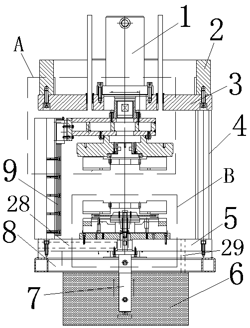
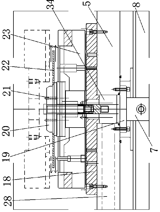
[0014] The present invention includes an upper hydraulic mechanism and a lower hydraulic mechanism; the upper hydraulic mechanism and the lower hydraulic mechanism are respectively equipped with an upper mold 16 and a lower mold 23, and cooperate with each other.

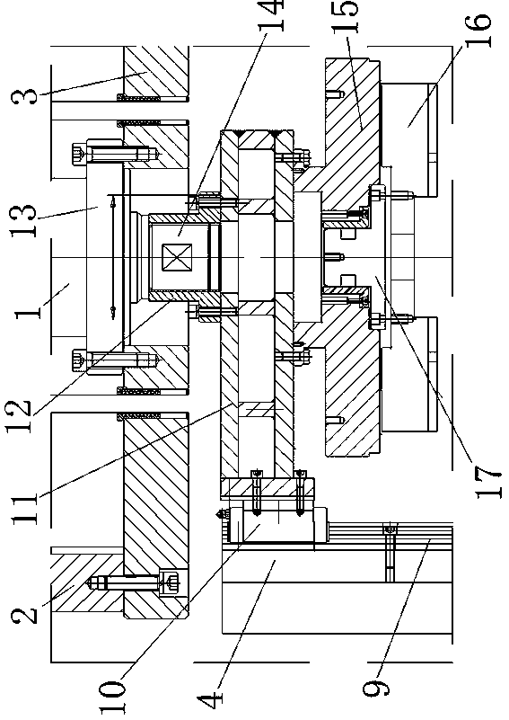
[0015] Upper hydraulic mechanism: the upper fixed plate 3 is fixedly installed on the upper end of the column 4 through the upper vertical plate 2, and the column 4, the upper vertical plate 2 and the upper fixed plate 3 are supporting mechanisms. The hydraulic cylinder body 1 of the hydraulic machine is fixed on the upper fixing plate 3 through the upper connecting plate 13, the hydraulic cylinder plug 14 of the hydraulic machine passes through the upper fixing plate 3 and is fixedly connected with the fixed connection body 12, and the fixed connection body 12 is fastened to the slide rail seat 11 by bolts On one side of the slide rail seat 11, a slide rail cover 10 is fixedly installed. The slide rail cover 10 and ...


PUM


Abstract

The invention discloses a clutch driven disc heat treatment machining tool, belongs to the technical field of clutch machining and aims to directly carry out quenching and leveling of a driven disc atthe same time. The tool comprises an upper hydraulic mechanism and a lower hydraulic mechanism. The tool is advantaged in that profiling and quenching are carried out at the same time, flattening precision of a workpiece is guaranteed, deformation of parts under the conditions of high temperature and high pressure can be prevented while the flatness requirement is met, flatness of the driven discis ensured by ensuring the deformation of the part, so the high-temperature leveling procedure is reduced, in the quenching and cooling process of the part, the heat balance flow of the quenching oilquantity can be adjusted, that the oil quantity is sufficient during quenching is guaranteed, and the part can obtain the good quenching effect.

Description

technical field [0001] The invention belongs to the technical field of clutch processing. Background technique [0002] The driven disc in the automobile clutch is a key part of the entire clutch, which directly affects the performance of the clutch. The driven disc is a thin-walled large-size part. During the production process, it is produced by quenching after carbonitriding and high-temperature leveling. Yes, the conditions are very harsh during use, and can only be used after heat treatment. When the driven disc is subjected to the joint action of tissue stress and thermal stress after heat treatment, the deformation of the parts is relatively large, and it needs to be leveled to be practical. The traditional leveling uses heating The flat mold uses high temperature and high pressure conditions to level the parts. The disadvantage is that the position of the parts after leveling under the high temperature and high pressure conditions is easy to deteriorate, and it is di...

Claims


Application Information

Patent Timeline
Patent Type & Authority Applications(China)
IPC IPC(8): B21D22/02B21D37/14C21D1/667C21D1/673C21D9/00
CPCB21D22/022B21D37/14C21D1/667C21D1/673C21D9/0068
Inventor 王璘阳张磊李欣刘明亮李筱隆姜伯冬张洪波隋延明李东辉
Owner CHANGCHUN YIDONG CLUTCH
Why Eureka
Try Eureka