
Plate shearing equipment for producing new energy automobile parts

A technology for new energy vehicles and parts, which is applied in the direction of shearing machine equipment, metal processing equipment, metal processing machinery parts, etc. It can solve the problems that affect the processing effect of objects, the blade cannot be easily disassembled, and the position is easy to shift, so as to ensure the income Accuracy of materials, guarantee of work quality, and improvement of versatility

Active Publication Date: 2020-03-27
友信宏科新能源(徐州)有限公司
View PDF8 Cites 7 Cited by
  • Summary
  • Abstract
  • Description
  • Claims
  • Application Information

AI Technical Summary

Problems solved by technology

[0003] However, there are still some disadvantages in the existing shearing equipment for the production of new energy auto parts. The blade cannot be easily disassembled during use, which affects the processing effect of the object. The universality of the device is low, and when the collection frame is collected in the base , the position is easy to shift, and when the collection frame is collecting objects, the objects are easy to be bumped. For this reason, we propose a shearing equipment for the production of new energy auto parts

Method used


Image

  • Plate shearing equipment for producing new energy automobile parts
  • Plate shearing equipment for producing new energy automobile parts
  • Plate shearing equipment for producing new energy automobile parts

Examples


Embodiment Construction

[0026] The following will clearly and completely describe the technical solutions in the embodiments of the present invention with reference to the accompanying drawings in the embodiments of the present invention. Obviously, the described embodiments are only some, not all, embodiments of the present invention. Based on the embodiments of the present invention, all other embodiments obtained by persons of ordinary skill in the art without making creative efforts belong to the protection scope of the present invention.

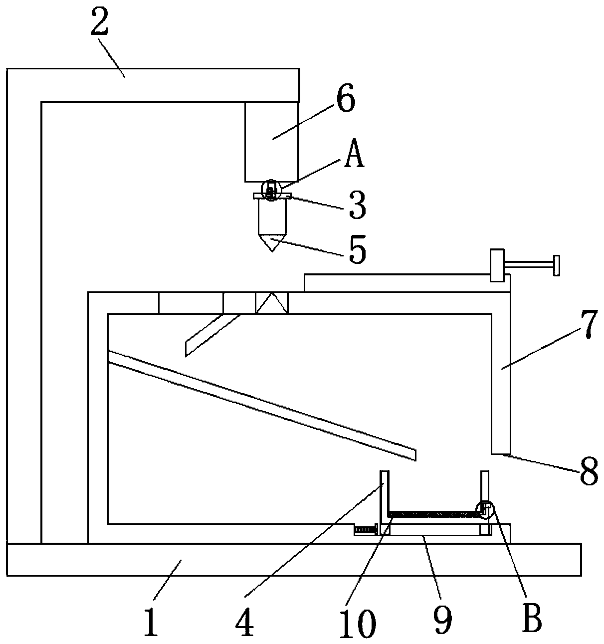
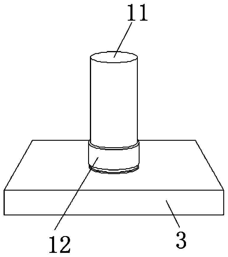
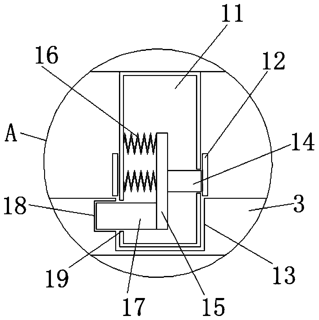
[0027] see Figure 1-6 , the present invention provides a technical solution: shearing equipment for the production of new energy automobile parts, including a base 1, a disassembly mechanism, a fixing mechanism, and a protection mechanism. The top surface of the base 1 is provided with a shearing equipment body 2, and the The inner top surface is provided with a cylinder 6, the bottom side surface of the cylinder 6 is provided with a connecting rod 11, one si...


PUM


Abstract

The invention discloses plate shearing equipment for producing new energy automobile parts. The plate shearing equipment comprises a base, a dismounting mechanism, a fixing mechanism and a protectionmechanism. A plate shearing equipment body is arranged on the top end surface of the base, and an air cylinder is arranged on the top end surface of the inner side of the plate shearing equipment body. A connecting rod is arranged on the surface of one side of the bottom end of the air cylinder, and a mounting plate is arranged on the surface of one side of the connecting rod. By means of a rubbersleeve, when the rubber sleeve is moved to one side, an extrusion column is elastically moved to one side under the acting force of a first spring, and a clamping column connected to one side of a first connecting plate is driven to move to one side under the acting force of the first spring, so that one end of the clamping column is separated from the interior of a first connecting hole, and thefixed state between the connecting rod and a mounting groove is opened. By means of an installation groove, the connecting rod conveniently slides to one side inside the installation groove.

Description

technical field [0001] The invention belongs to the technical field of auto parts processing, and in particular relates to shearing equipment for the production of new energy auto parts. Background technique [0002] Auto parts processing is the units that constitute the whole of auto parts processing and the products that serve the processing of auto parts. With the increasingly fierce competition in the auto parts processing market, the popularization of the concept of environmental protection, and the continuous upgrading and application of technology, in the auto parts processing In the process, shearing equipment for the production of new energy auto parts is needed. [0003] However, there are still some disadvantages in the existing shearing equipment for the production of new energy auto parts. The blade cannot be easily disassembled during use, which affects the processing effect of the object. The universality of the device is low, and when the collection frame is ...

Claims


Application Information

Patent Timeline
Patent Type & Authority Applications(China)
IPC IPC(8): B23D27/00B23D35/00B21D43/22B23Q11/00
CPCB21D43/22B23D27/00B23D35/00B23Q11/0032
Inventor 李萌
Owner 友信宏科新能源(徐州)有限公司
Learn More