Small-diameter shaft shoulder stirring head

A stirring head and small-diameter technology, applied in non-electric welding equipment, welding equipment, metal processing equipment, etc., can solve problems such as weld hole defects, limited spindle speed, and influence on weld quality

Inactive Publication Date: 2020-03-27
HUNAN JOINFRONT WELDING TECH
View PDF12 Cites 6 Cited by
  • Summary
  • Abstract
  • Description
  • Claims
  • Application Information

AI Technical Summary

Problems solved by technology

[0005] If the stirring head is reduced proportionally, during the welding process, due to the limited spindle speed, the heat generated by the stirring head is too small, the stirring force is too small and other factors that are not conducive to welding, which may easily lead to insufficient plasticization of the welding material and insufficient flow filling. , resulting in internal hole defects in the weld, seriously affecting the quality of the weld

Method used


Image

  • Small-diameter shaft shoulder stirring head
  • Small-diameter shaft shoulder stirring head
  • Small-diameter shaft shoulder stirring head

Examples


Embodiment 1

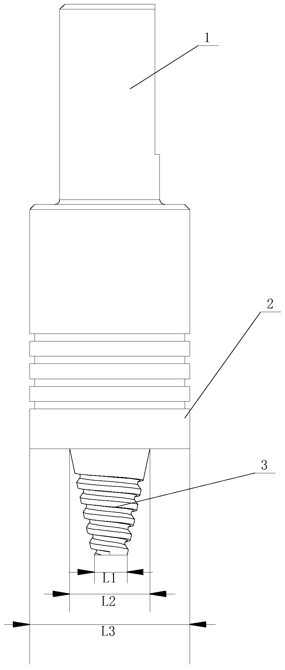
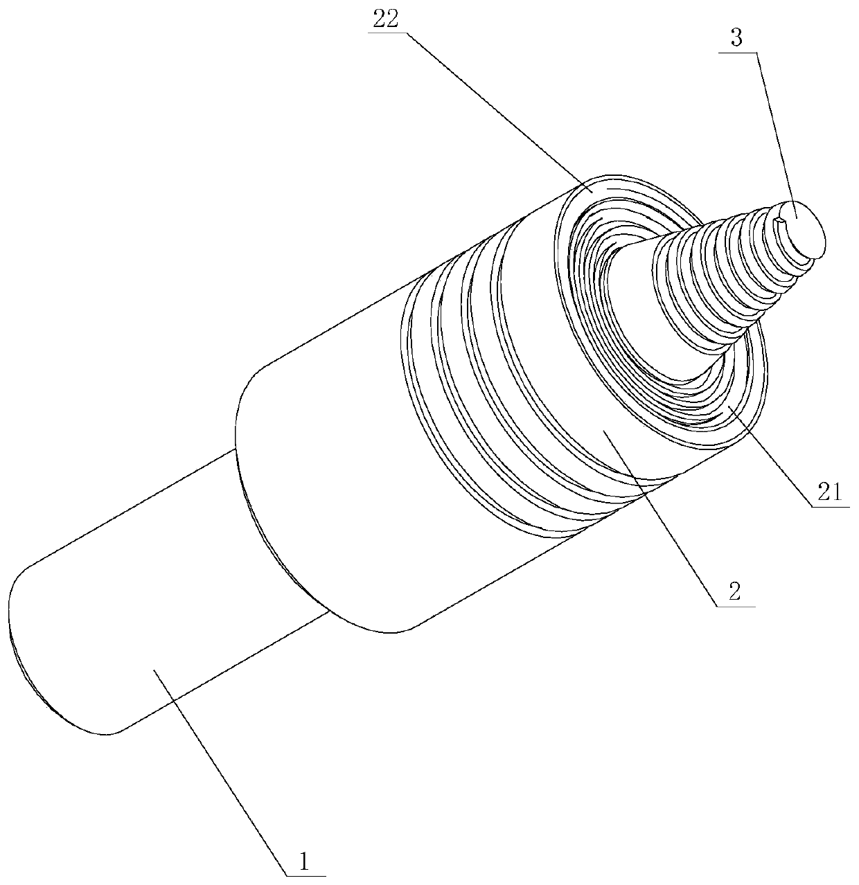
[0064] Such as Figure 1 to Figure 3 As shown, the first embodiment of the small-diameter shoulder stirring head of the present invention includes a clamping part 1, a shaft shoulder part 2 and a stirring needle 3 connected in sequence, and the diameter of the tip part 31 of the stirring needle 3 is defined as L1, and the definition The diameter of the needle base 32 of the stirring needle 3 is L2, and the diameter of the defined shaft shoulder 2 is L3, L1: L2 = 1: 1 ~ 1.7; L2: L3 = 1: 1.8 ~ 2.5; the end face of the shaft shoulder 2 is included in The stirring zone 21 close to the stirring needle 3 in the radial direction and the envelope zone 22 far away from the stirring needle 3, the envelope zone 22 is set as a gentle surface for wrapping together and forging plastic metal, and the stirring zone 21 is provided with a surface for increasing the frictional moment non-concentric circle structure. In this structure, the small-diameter shoulder stirring head is adopted. Accord...

Embodiment 2

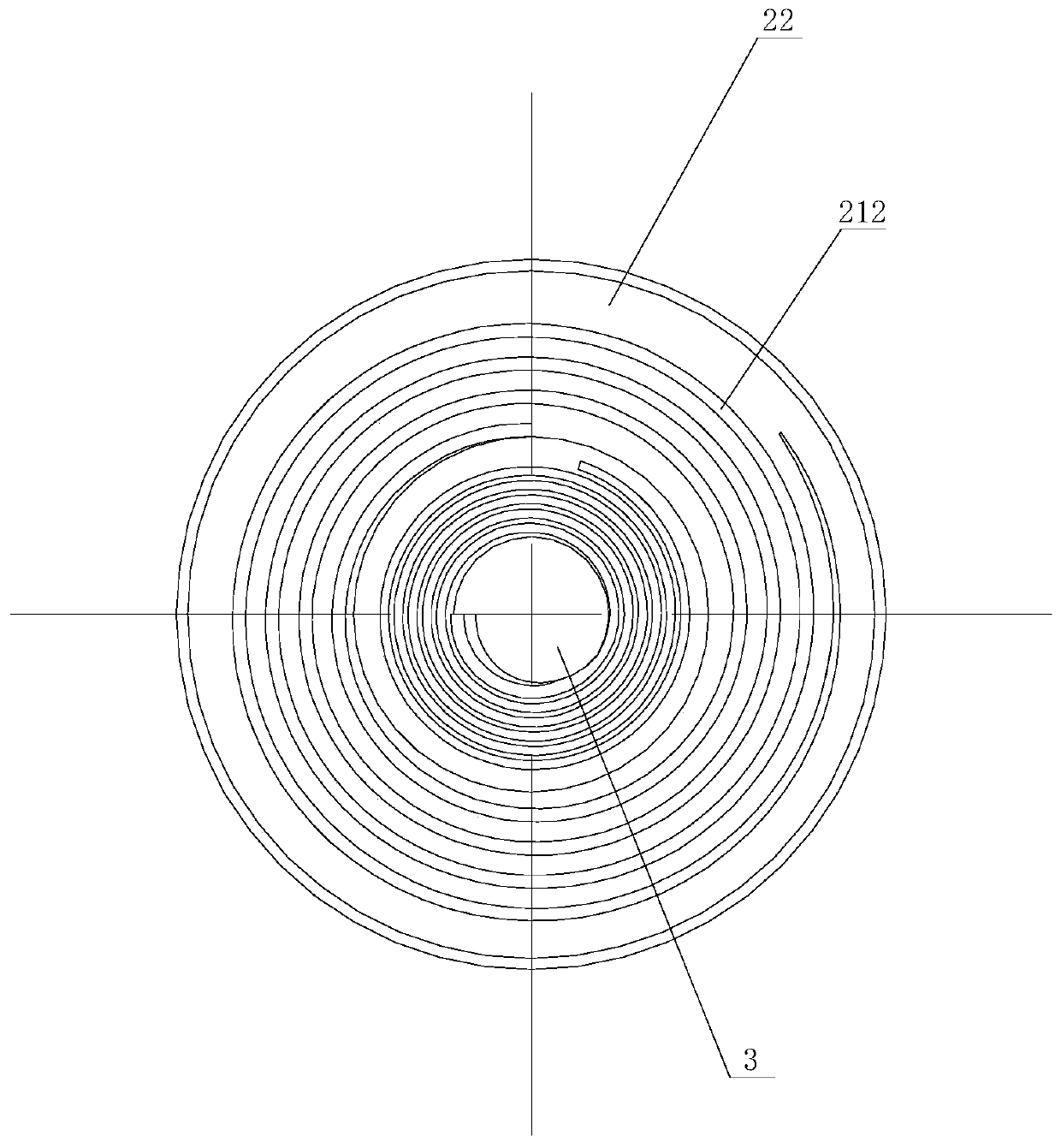
[0070] Such as Figure 4 As shown, in the second embodiment of the small-diameter shoulder stirring head of the present invention, the stirring head is basically the same as that of Embodiment 1, the only difference is that in this embodiment, the groove 212 is set as an open-loop type formed by a curve curved groove. The open-loop curved groove can increase the stirring and heat production effect of the stirring zone 21 .

[0071] In this embodiment, the open-loop curved groove is in the form of a continuous single groove. The friction force is increased, and the weld metal in the enveloping area 22 is periodically impacted, which is beneficial to reducing the metal oxide film.

Embodiment 3

[0073] Such as Figure 5 As shown, the third embodiment of the small-diameter shoulder stirring head of the present invention is basically the same as that of embodiment 1, the only difference being that in this embodiment, the open-loop curved grooves are in the form of separate multi-grooves. The friction force is increased, and the weld metal in the enveloping area 22 is periodically impacted, which is beneficial to reducing the metal oxide film.

[0074] In this embodiment, a concentric circle structure is provided between the gentle surface and the non-concentric circle structure. The concentric circle structure can increase the enveloping effect under the condition of radial flow.


PUM


Abstract

The invention discloses a small-diameter shaft shoulder stirring head. The small-diameter shaft shoulder stirring head comprises a clamping part, a shaft shoulder part and a stirring needle which aresequentially connected, the diameter of the needle tip part of the stirring needle is defined as L1, the diameter of the needle root part of the stirring needle is defined as L2, the diameter of the shaft shoulder part is defined as L3, the ratio of L1 to L2 is equal to 1 to 1-1.7, the ratio of L2 to L3 is equal to 1 to 1.8-2.5, the end face of the shaft shoulder part comprises a stirring area close to the stirring needle in the radial direction and an envelope area away from the stirring needle, and the stirring area is provided with a non-concentric circle structure for improving the friction torque. The stirring head has the advantages that stirring and heat production effects can be increased, welding defects can be avoided, and the stirring head is suitable for producing narrow-edge welds.

Description

technical field [0001] The invention mainly relates to friction stir welding technology, in particular to a small-diameter shaft shoulder stirring head. Background technique [0002] There is no mature theory for the design of the structure and size of the mixing head, and most of them are designed according to experience. [0003] Generally, the stirring pin of the stirring head adopts equal-pitch thread, the diameter of the root of the stirring pin is generally equal to the welding thickness, and the ratio of the root diameter of the stirring pin to the diameter of the shaft shoulder is generally 1:2.5~3. Because the diameter of the shaft shoulder of the general stirring head is larger, the weld seam formed is wider, and the heat-affected zone will be larger, which affects the mechanical properties of the weld seam and also affects the appearance of the weld seam. At the same time, because the shaft shoulder is large, it cannot be produced when it encounters a narrow edge...

Claims


Application Information

Patent Timeline
Patent Type & Authority Applications(China)
IPC IPC(8): B23K20/12
CPCB23K20/12B23K20/122B23K20/1245B23K20/1255
Inventor 钟南李志明李贤清周长兴汤雨竹
Owner HUNAN JOINFRONT WELDING TECH
Why Eureka
Try Eureka