Hot-dip-galvanized steel welding, manufacturing and machining process

A hot-dip galvanized and processing technology, applied in the field of steel welding, can solve the problems of automatic loading and unloading, C-shaped steel welding, and reduced welding firmness, so as to reduce efficiency, increase manpower and material resources, and increase efficiency. Effect

Active Publication Date: 2020-03-27
扬州澳洋顺昌金属材料有限公司
6 Cites 4 Cited by

AI-Extracted Technical Summary

Problems solved by technology

[0005] The present invention can solve the problem that existing equipment cannot weld C-shaped steels of different sizes on the same device when performing mobile welding on C-shaped steels, thereby increasing the welding cost when welding C-shaped steels of different sizes, and at the same time , it is impossible to weld the C-sha...

Abstract

The invention relates to a hot-dip-galvanized steel welding, manufacturing and machining process. The hot-dip-galvanized steel welding, manufacturing and machining process adopts a bottom plate, a bearing device, clamping devices, transmission devices and a welding device main body, wherein the bearing device is installed at the upper end of the bottom plate, the clamping devices are symmetricallyarranged at the upper end of the bearing device, the clamping devices are connected with the bearing device in a sliding fit mode, and the transmission devices are connected to the outer sides of theclamping devices. According to the hot-dip-galvanized steel welding, manufacturing and machining process, the difficulties that the welding cost is increased when C-shaped steel materials with different sizes are welded because the C-shaped steel with different sizes cannot be welded on the same device when existing equipment conducts movable welding on the C-shaped steel, the phenomenon of missing welding is prone to occur since the C-shaped steel cannot be welded from two sides at the same time, the firmness of welding is reduced, automatic feeding and discharging functions cannot be achieved, the production steps are increased, manpower and material resources are increased and the welding efficiency is reduced are solved.

Application Domain

Welding/cutting auxillary devicesAuxillary welding devices +2

Technology Topic

Machining processMaterial resources +2

Image

  • Hot-dip-galvanized steel welding, manufacturing and machining process
  • Hot-dip-galvanized steel welding, manufacturing and machining process
  • Hot-dip-galvanized steel welding, manufacturing and machining process

Examples

  • Experimental program(1)

Example Embodiment

[0035] The embodiments of the present invention will be described in detail below with reference to the accompanying drawings, but the present invention can be implemented in a variety of different ways defined and covered by the claims.
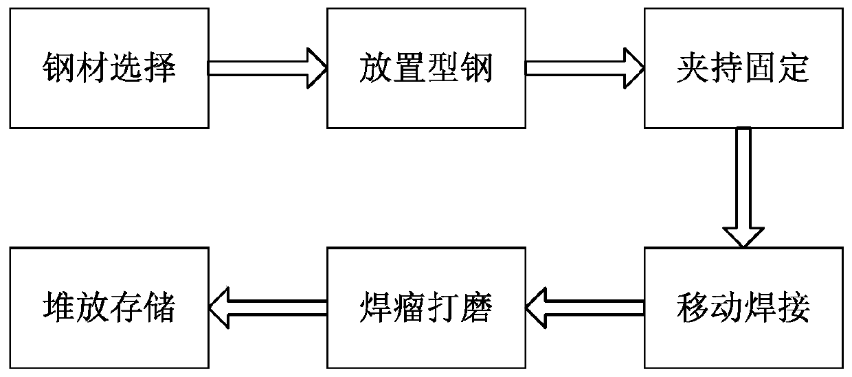
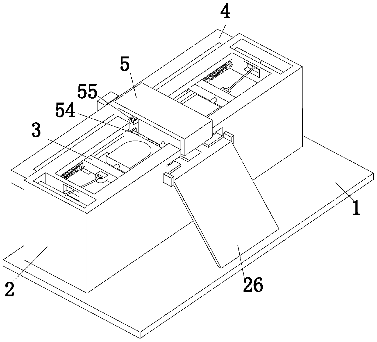
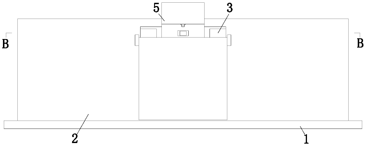
[0036] Such as Figure 1 to Figure 8 As shown, a hot-dip galvanized steel welding manufacturing process uses a hot-dip galvanized steel welding device. The hot-dip galvanized steel welding device includes a bottom plate 1, a receiving device 2, a clamping device 3. The transmission device 4 and the welding device 5 are characterized in that: the specific method for welding the hot-dip galvanized steel with the above-mentioned hot-dip galvanized steel welding device is as follows:
[0037] S1. Steel selection: Manually select the C-shaped steel to be welded, and manually remove the dust, residue and other residues on its surface;
[0038] S2. Placing section steel: manually place a number of C-shaped steels in the carrying device 2 in sequence, and the carrying device 2 will carry and lift up the C-shaped steel;
[0039] S3. Clamping and fixing: After the placement of step S2 is completed, the supporting device 2 lifts the C-shaped steel to the clamping device 3, and the clamping device 3 clamps and fixes the C-shaped steel;
[0040] S4. Mobile welding: After step S3 is completed, the welding device 5 simultaneously welds the two C-shaped steels from the upper and lower ends;
[0041] S5. Welding bead polishing: Take out the welded C-shaped steel manually, and polish the welding bead produced by welding;
[0042] S6. Stacking and storage: After step S5 is completed, manually stack the C-shaped steel for easy storage and placement.
[0043] A supporting device 2 is installed at the upper end of the bottom plate 1, and a clamping device 3 is symmetrically arranged on the upper end of the supporting device 2. The clamping device 3 is connected to the supporting device 2 by a sliding fit, and a transmission device 4 is connected to the outside of the clamping device 3. The transmission device 4 is installed on the receiving device 2, a welding device 5 is arranged in the middle of the two clamping devices 3, and the welding device 5 is installed on the receiving device 2.
[0044] The bearing device 2 includes a bearing seat 21, a second telescopic rod 22, a jacking spring 23, a placing plate 24, a limiting plate 25 and a blanking plate 26, and the bearing seat 21 is installed on the bottom plate 1. , The receiving seat 21 has a T-shaped structure, the receiving seat 21 is symmetrically provided with a rectangular through hole, the rectangular through hole is provided with a semi-cylinder, and the inner bottom of the rectangular through hole is provided with a second telescopic rod 22 and a second telescopic rod 22 Installed on the bottom plate 1, the outer surface of the second telescopic rod 22 is installed with a jacking spring 23, the top of the second telescopic rod 22 is installed with a placement plate 24, the upper end of the rectangular through hole is provided with a rectangular groove, and the inside of the rectangular groove is symmetrically installed with a limit Plate 25, the side wall of the rectangular groove is symmetrically provided with sliding grooves, the middle of the sliding groove is provided with grooves, the grooves are matched with the limit rod 325, and the front end of the bearing seat 21 is installed with a blanking plate 26. In specific work, first, Manually place the C-shaped steel on the placement plate 24. After that, the No. 2 telescopic rod 22 drives the placement plate 24 upward through the jacking spring 23 to realize the automatic feeding function. Finally, after the welding is completed, the blanking plate 26 Used for blanking C-shaped steel.
[0045] The clamping device 3 includes a clamping rod 31, a limiting mechanism 32, a clamping spring 33, a threaded rod 34, a clamping plate 35, a telescopic rod 36, a pushing block 37 and a clamping mechanism 38. The clamping rod 31 is connected to the receiving device 2 by a sliding fit. The clamping rod 31 is slidably connected to the limiting mechanism 32. The outer end of the clamping rod 31 is symmetrically provided with clamping springs 33, and the clamping springs 33 are installed on the receiving device. On the device 2, the inner end of the clamping rod 31 is connected with a threaded rod 34 through a bearing, and a clamping plate 35 is screwed on the threaded rod 34. A telescopic rod 36 is symmetrically arranged on the outer side of the threaded rod 34, and the first telescopic rod 36 is installed in the clamp. On the holding plate 35, the inner end of the threaded rod 34 is connected with a pushing block 37 through a bearing, and the pushing block 37 is slidably connected to the clamping plate 35. The inner end of the pushing block 37 is evenly provided with a clamping mechanism 38. The clamping mechanism 38 is slidingly fitted The method is connected with the clamping plate 35. During specific work, the threaded rod 34 is manually rotated according to the size of the C-shaped steel. The threaded rod 34 drives the clamping mechanism 38 through the push block 37, and then the limit mechanism 32 is driven by the threaded rod 34 The clamping mechanism 38 clamps and fixes the C-shaped steel.
[0046] The limit mechanism 32 includes a top rod 321, an inclined sliding block 322, a connecting spring 323, a transmission rod 324, a limit rod 325, and a limit spring 326. The top rod 321 is clamped by a sliding fit. The rod 31 is connected, the outer end of the ejector rod 321 is connected with the transmission device 4, the inner end of the ejector rod 321 is equipped with a connecting spring 323, the outer surface of the ejector rod 321 is symmetrically installed with oblique sliders 322, and the oblique slider 322 is provided with a transmission rod outside 324, the transmission rod 324 is slidably connected with the clamping rod 31, the outer end of the transmission rod 324 is installed with a limit rod 325, the limit rod 325 is slidably connected with the clamping rod 31, and the outer surface of the transmission rod 324 is provided with a limit spring 326, a limit spring 326 is installed on the limit rod 325. During specific work, at the beginning of welding, the top rod 321 moves the limit rod 325 through the inclined slider 322 to realize the function of limit. After the welding, the top rod 321 The force is applied to move backwards, thereby realizing the function of resetting the limit rod 325, which facilitates the feeding of the C-shaped steel.
[0047] The clamping mechanism 38 includes an arc-shaped plate 381, a support rod 382, ​​a support plate 383, and a support spring 384. The support rod 382 is connected to the clamping plate 35 by a sliding fit, and the support rod 382 is provided with The arc plate 381, the inner end of the support rod 382 is equipped with a support plate 383, the outer surface of the support rod 382 is provided with a support spring 384, and the support spring 384 is installed on the support plate 383. During specific work, the pushing block 37 is driven by the arc plate 381 The support plate 383 moves to realize the function of clamping and fixing the C-shaped steel.
[0048] The transmission device 4 includes a transmission frame 41, a drive motor 42, a No. 1 helical gear 43, a linkage rod 44, a No. 2 helical gear 45, a winding wheel 46, and a wire rope 47. The transmission frame 41 is installed on the bearing seat. 21, the rear end of the transmission frame 41 is equipped with a driving motor 42. The output shaft of the driving motor 42 is equipped with a helical gear 43. The first helical gear 43 is located in the transmission frame 41. The linkage rod 44 is mounted on the transmission frame 41 through bearings. The outer gear of the linkage rod 44 is connected with the second helical gear 45. The second helical gear 45 is mounted on the transmission frame 41 through bearings. The front end of the second helical gear 45 is installed. There is a winding wheel 46. The winding wheel 46 is mounted on the bearing seat 21 through a bearing. A wire rope 47 is installed on the winding wheel 46. The inner end of the wire rope 47 is connected to the ejector rod 321. During the specific work, the C-shaped steel When feeding, the drive motor 42 is manually started, and the drive motor 42 drives the reel 46 to move through the linkage rod 44, thereby driving the limit mechanism 32 to move backwards to realize the feeding function of the receiving device 2, and then reverse drive The motor 42 and the driving motor 42 drive the limit mechanism 32 to reset through the winding wheel 46, thereby realizing the function of fixing and limiting the C-shaped steel.
[0049] The two ends of the linkage rod 44 are equipped with helical gears. The helical gear located on the inner side is connected to the first helical gear 43, and the helical gear located on the outer side is connected to the second helical gear 45. In specific work, the helical gear serves as a connecting transmission effect.
[0050] The welding device 5 includes a welding frame 51, a sliding frame 52, a welding head 53, a No. 1 electric push rod 54 and a No. 2 electric push rod 55. The welding frame 51 is installed on the bearing seat 21, and the welding frame 51 A sliding frame 52 is installed symmetrically inside the sliding frame 52. A welding head 53 is slidably connected to the inside of the sliding frame 52. The rear end of the welding head 53 is connected to a No. 1 electric push rod 54. The No. 1 electric push rod 54 is installed on the welding frame 51. There is a No. 2 electric push rod 55 between the rods 54, and the No. 2 electric push rod 55 is installed on the welding frame 51. During specific work, first, manually start the No. 1 electric push rod 54, and the No. 1 electric push rod 54 drives the welding head. After the 53 moves, the welding head 53 performs mobile welding on the two C-shaped steels. Finally, after the welding is completed, the second electric push rod 55 is manually activated, and the second electric push rod 55 pushes and cuts the C-shaped steel.
[0051] When welding: the first step: first, manually adjust the clamping mechanism 38 according to the size of the C-shaped steel to be welded, and then manually place the C-shaped steel on the placement plate 24 in the bearing seat 21, and finally, The second telescopic rod 22 drives the placement plate 24 to be lifted through the lifting spring 23;
[0052] Step 2: First, manually start the drive motor 42. The drive motor 42 drives the clamping device 3 to move backward through the winding wheel 46. After that, the second telescopic rod 22 pushes the C-shaped steel into the clamping device through the lifting spring 23. 3 inner end, finally, reverse the drive motor 42, the drive motor 42 drives the clamping device 3 to move through the winding wheel 46, the clamping spring 33 drives the clamping device 3 to reset, and the drive motor 42 is manually closed;
[0053] Step 3: First, manually start the No. 1 electric push rod 54. The No. 1 electric push rod 54 drives the welding head 53 to move and weld the two C-shaped steels. After the welding is completed, the flashlight starts the No. 2 electric push rod 55 , No. 2 electric push rod 55 pushes and cuts the C-shaped steel, and finally, No. 1 electric push rod 54 and No. 2 electric push rod 55 are reset;
[0054] Step 4: Repeat the second and third steps to achieve continuous welding. After the welding is completed, stack the C-shaped steel and the welding is completed.
[0055] The above descriptions are only preferred embodiments of the present invention and are not used to limit the present invention. For those skilled in the art, the present invention may have various modifications and changes. Any modification, equivalent replacement, improvement, etc., made within the spirit and principle of the present invention shall be included in the protection scope of the present invention.

PUM

no PUM

Description & Claims & Application Information

We can also present the details of the Description, Claims and Application information to help users get a comprehensive understanding of the technical details of the patent, such as background art, summary of invention, brief description of drawings, description of embodiments, and other original content. On the other hand, users can also determine the specific scope of protection of the technology through the list of claims; as well as understand the changes in the life cycle of the technology with the presentation of the patent timeline. Login to view more.

Similar technology patents

Device and method for testing leakage of air pressure of lifting seat

ActiveCN105738043AReduce efficiencycostly
Owner:TBEA SHENYANG TRANSFORMER GRP CO LTD

Exhaust gas purification system for a fuel cell or a fuel cell stack

InactiveUS20100316927A1reduce efficiencylow power requirement
Owner:FORSCHUNGSZENTRUM JUELICH GMBH

Preparation method of frozen crusty pancake blank

PendingCN114128737AAdditional production stepsEasy operation
Owner:新疆农业科学院农产品贮藏加工研究所

Digital intelligent balance weight device for electrified railway compensation balance weight factory

PendingCN114674406AManual labor intensity is highReduce efficiency
Owner:CHINA CREC RAILWAY ELECTRIFICATION BUREAU GRP +1

Classification and recommendation of technical efficacy words

  • Additional production steps

Preparation method of frozen crusty pancake blank

PendingCN114128737AAdditional production stepsEasy operation
Owner:新疆农业科学院农产品贮藏加工研究所
Why Eureka
Try Eureka