Semi-circular grooving machine for end part of steel pipe

A technology of semi-circular grooves and steel pipes, which is applied in the direction of metal processing machinery parts, clamping, support, etc., can solve the problems such as the difficulty of opening semi-circular grooves and the inability to groove steel pipes, etc., and achieve the effect of simple structure, convenient use and convenient use

Pending Publication Date: 2020-03-27
江西省致能智造产业技术研究有限公司
View PDF0 Cites 2 Cited by
  • Summary
  • Abstract
  • Description
  • Claims
  • Application Information

AI Technical Summary

Problems solved by technology

[0004] The purpose of the present invention is to solve the shortcoming that the diameter of the existing cutting tool is too small, so that when cutting the end of the steel pipe, it is impossible to directly use the rotating cutting tool to cut the steel pipe. A steel pipe end semicircle groove machine

Method used


Image

  • Semi-circular grooving machine for end part of steel pipe
  • Semi-circular grooving machine for end part of steel pipe
  • Semi-circular grooving machine for end part of steel pipe

Examples


Embodiment 1

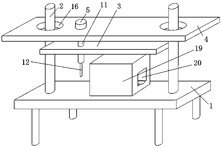
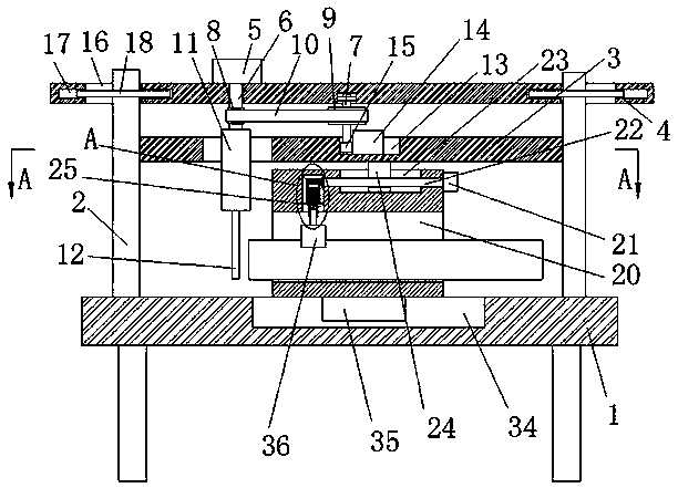
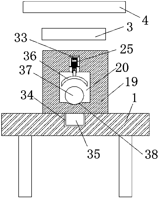
[0026] Embodiment one: refer to Figure 1-5 , a semicircular slotting machine at the end of a steel pipe, comprising a base 1, two symmetrically arranged support rods 2 are fixedly installed on the top of the base 1, and the same fixed plate 3 is fixedly installed on the side of the two support rods 2 close to each other, The tops of the two support rods 2 are slidably connected to the same top plate 4, the top of the top plate 4 is fixedly mounted with the first motor 5, the output shaft of the first motor 5 is fixedly mounted with the first rotating rod 6, and the bottom of the top plate 4 is rotatably connected There is a second rotating rod 7, the first rotating rod 6 is connected to the second rotating rod 7, the bottom end of the first rotating rod 6 is fixedly installed with a fixing seat 11, and the bottom of the fixing seat 11 runs through the fixing plate 3 and is fixedly connected with a tool 12. The top of the base 1 is slidingly connected with a moving seat 19, an...

Embodiment 2

[0036] Embodiment two: refer to Figure 1-5 , a semi-circular slotting machine for the end of a steel pipe, comprising a base 1, two symmetrically arranged support rods 2 are welded on the top of the base 1, and the same fixing plate 3 is welded on the side of the two support rods 2 close to each other, two The top of the support rod 2 is slidingly connected with the same top plate 4, the top of the top plate 4 is welded with the first motor 5, the output shaft of the first motor 5 is welded with the first rotating rod 6, and the bottom of the top plate 4 is connected with the second rotating rod. Rod 7, the first rotating rod 6 and the second rotating rod 7 are connected in transmission, the bottom end of the first rotating rod 6 is welded with a fixed seat 11, the bottom of the fixed seat 11 runs through the fixed plate 3 and is fixedly connected with a cutter 12, the base 1 The top is slidingly connected with a moving seat 19, and one side of the moving seat 19 is provided ...


PUM


Abstract

The invention belongs to the field of steel pipe grooving equipment, and particularly relates to a semi-circular grooving machine for the end part of a steel pipe. According to the semi-circular grooving machine, aiming at the problem that semi-circular groove forming is difficult due to the fact that when a semi-circular groove is formed on the end part of the steel pipe, the rotary cutter cannotbe directly used for grooving the steel pipe due to the existing cutter with the too small diameter. The following scheme is now presented, the semi-circular grooving machine comprises a base, wherein two symmetrically arranged supporting rods are fixedly mounted on the top of the base, one side, close to each other, of the two supporting rods is fixedly provided with the same fixing plate, the top ends of the two supporting rods are slidably connected with the same top plate, the top of the top plate is fixedly provided with a first motor, the output shaft of the first motor is fixedly provided with a first rotating rod, the bottom of the top plate is rotatably connected with a second rotating rod, the first rotating rod is in transmission connection with the second rotating rod, and thebottom end of the first rotating rod is fixedly provided with a fixing base. The semi-circular grooving machine is simple in structure and convenient to use, the semi-circular grooving machine can quickly form the semi-circular groove on the steel pipe, and the semi-circular grooving machine is convenient for people to use.

Description

technical field [0001] The invention relates to the technical field of steel pipe grooving equipment, in particular to a semicircular grooving machine for steel pipe ends. Background technique [0002] Steel pipe is a metal part commonly used in mechanical equipment and people's lives. There are many types of steel pipes, including general steel pipes, low and medium pressure boiler steel pipes, high-pressure boiler steel pipes, alloy steel pipes, stainless steel pipes, petroleum cracking pipes, and carbon thin-walled steel pipes, alloy thin-walled steel pipes, stainless steel thin-walled steel pipes, and special-shaped steel pipes. . In the process of processing steel pipes into required mechanical equipment, various operations such as cutting, drilling, and welding are required for steel pipes. There are many types of cutting operations for steel pipes. The simplest is to cut off steel pipes, and then according to It is required to cut the steel pipe into a certain angle...

Claims


Application Information

Patent Timeline
Patent Type & Authority Applications(China)
IPC IPC(8): B23Q3/06B23Q1/25B23Q5/22
CPCB23Q1/25B23Q3/06B23Q3/062B23Q3/064B23Q5/22
Inventor 白聚勇张晓昊董国辉翟秀军刘燕鹏
Owner 江西省致能智造产业技术研究有限公司
Why Eureka
Try Eureka