Visual servo and manipulator based automatic docking system

A technology of automatic docking and visual servoing, which is applied in the directions of manipulators, program-controlled manipulators, liquid conveying devices, etc., can solve the problems of inability to meet the load of the aircraft docking process, unfavorable continuous operations for refueling operators, and high labor intensity of personnel. The effect of dispatching preparation time, reducing manual information transmission links, and improving docking control accuracy

Active Publication Date: 2020-03-27
CSSC SYST ENG RES INST
View PDF5 Cites 9 Cited by
  • Summary
  • Abstract
  • Description
  • Claims
  • Application Information

AI Technical Summary

Problems solved by technology

[0002] At present, support operations involving the docking of support equipment joints and aircraft fuselage interfaces (such as aircraft oil receiving ports) are all completed by manpower. Taking aircraft refueling as an example, maintenance personnel are required to complete information interaction, transfer of refueling joints, etc., while refueling The dragging of the hose and the docking of the refueling joint are completely dependent on manpower, the support efficiency is low, it takes up a lot of personnel, and the labor intensity is high, which is not conducive to the long-term continuous operation of refueling operators
At present, the technical solution based on the linkage between vision and robotic arm has been applied in industrial fields such as welding and sorting. However, due to the characteristics of small load, low precision and high repetition in many applications, it cannot meet the requirements of heavy load and high precision in the process of aircraft docking. There is no automatic docking system for aircraft support in China

Method used


Image

  • Visual servo and manipulator based automatic docking system
  • Visual servo and manipulator based automatic docking system
  • Visual servo and manipulator based automatic docking system

Examples


Embodiment Construction

[0035] The technical solution of the present invention will be further explained and described in detail according to the accompanying drawings and specific embodiments.

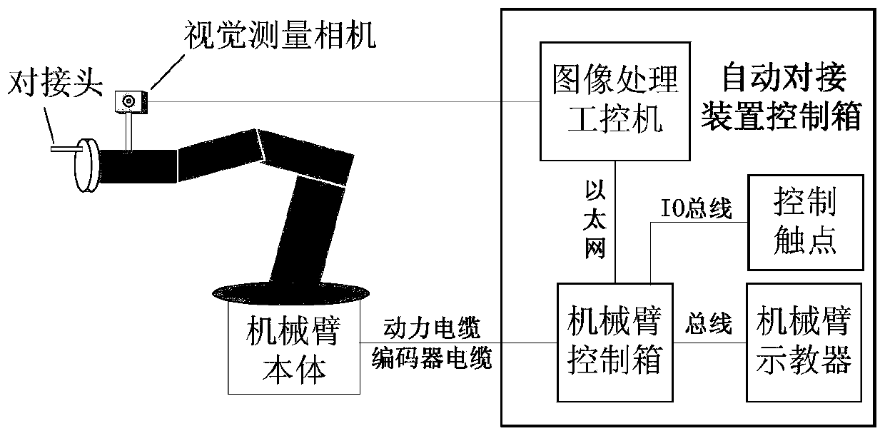
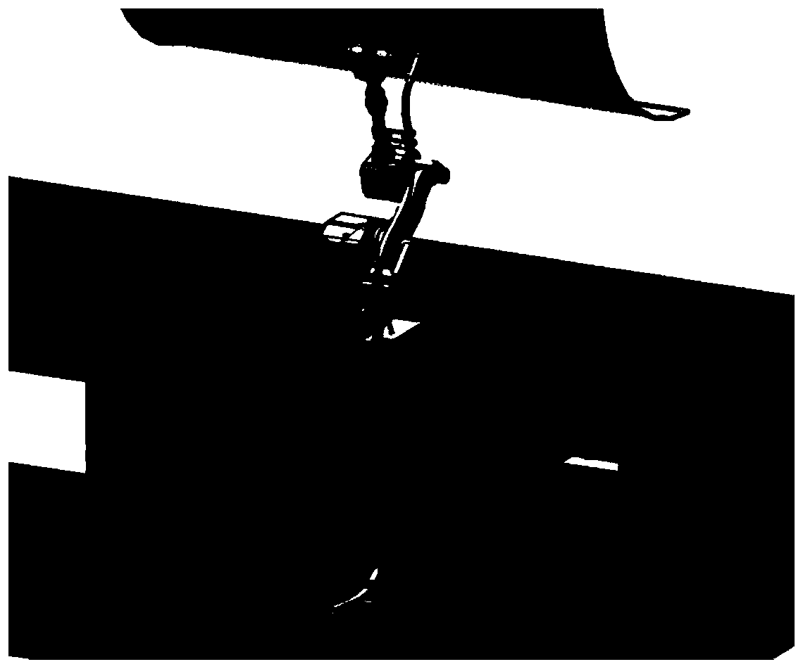
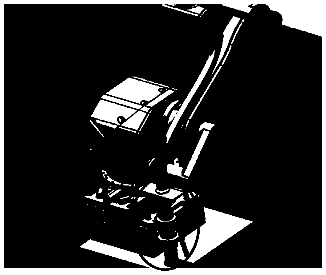
[0036] The robot arm automatic docking system based on visual servo is mainly composed of the robot arm body, the robot arm control box and the teaching pendant, the visual measurement camera and the image processing industrial computer. The basic dynamic docking system is shown in the figure figure 1 , the schematic diagram of the automatic docking system is shown in figure 2 , the block diagram of the automatic docking system is as follows Figure 5 shown.

[0037] The body of the robotic arm is fixedly connected to the joints of the aircraft support equipment, and can change the posture of the joints by adjusting the state of its own joints. The visual measurement camera and the image processing industrial computer capture the aircraft fuselage interface by taking pictures of the aircraft fuselage, and...


PUM


Abstract

The invention relates to a visual servo and manipulator based automatic docking system. The system is characterized by comprising a manipulator body, a manipulator control box, a vision measuring camera and an image processing industrial control computer, wherein the manipulator body is fixedly connected with a joint of aircraft support equipment, and the joint position can be changed by adjustingeach joint state of the manipulator body; the vision measuring camera and the image processing industrial control computer capture an airplane fuselage joint by shooting an airplane fuselage image, the target position of the manipulator body is calculated by a vision servo method, and the target position is sent to the manipulator control box through Ethernet; and the manipulator control box controls a manipulator end joint according to the docking process and target position command, and finally automatic docking is achieved. The automatic docking system greatly improves docking control precision, efficiency and information level, and can achieve downsizing and efficiency improving.

Description

technical field [0001] The invention relates to the field of aircraft support, in particular to an automatic docking system of a manipulator based on visual servoing. Background technique [0002] At present, support operations involving the docking of support equipment joints and aircraft fuselage interfaces (such as aircraft oil receiving ports) are all completed by manpower. Taking aircraft refueling as an example, maintenance personnel are required to complete information interaction, transfer of refueling joints, etc., while refueling The dragging of the hose and the docking of the refueling joint are completely dependent on manpower, the support efficiency is low, it takes up a lot of personnel, and the labor intensity is high, which is not conducive to the long-term continuous combat of refueling operators. At present, the technical solution based on the linkage between vision and robotic arm has been applied in industrial fields such as welding and sorting. However, ...

Claims


Application Information

Patent Timeline
Patent Type & Authority Applications(China)
IPC IPC(8): B25J9/16B64F1/28
CPCB25J9/1669B25J9/1697B64F1/28
Inventor 姜广文侯腾宋磊朱永丽胡靖
Owner CSSC SYST ENG RES INST
Why Eureka
Try Eureka