Body smart shelf
A main body frame and main body technology, applied in the field of main body intelligent shelves, can solve the problems of inconvenient access, large shelf space, long construction period, etc., and achieve the effects of convenient installation and dismantling, short construction period and low cost
- Summary
- Abstract
- Description
- Claims
- Application Information
AI Technical Summary
Problems solved by technology
Method used
Image
Examples
Embodiment 1
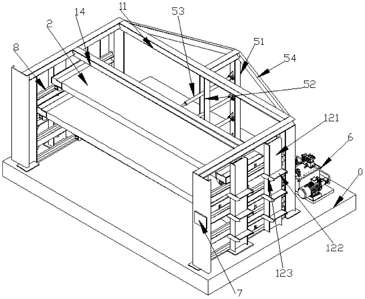
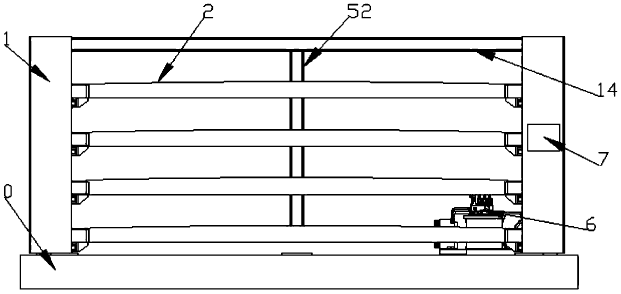
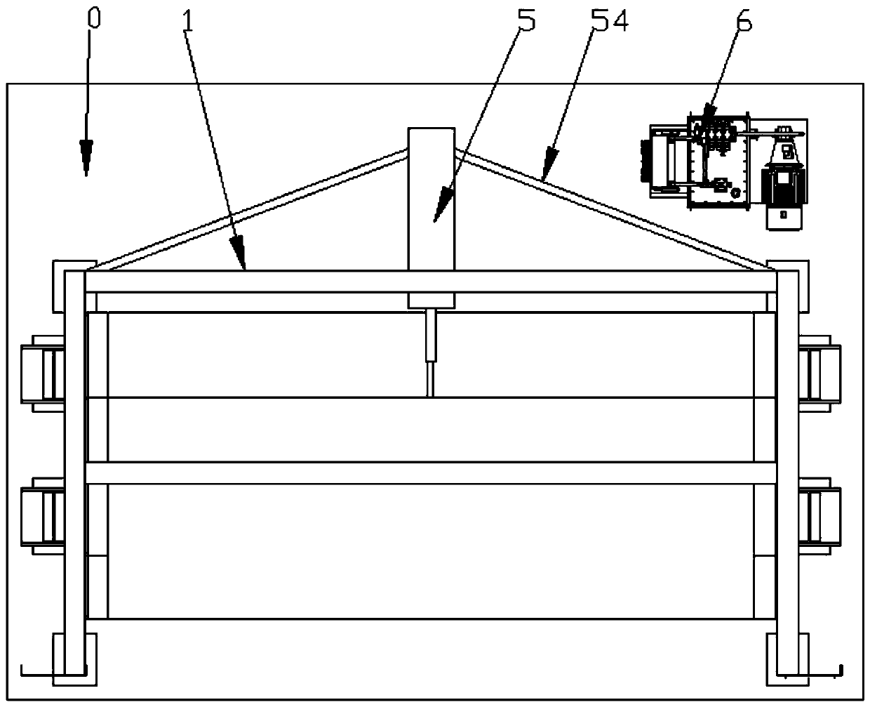
[0033] The main intelligent shelf, such as Figure 1-Figure 3 As shown, it includes a main frame 1 and a tray 2 with a base 0. The main frame 1 is installed on the base 0. The main frame 1 is provided with a track 8, and the track 8 located on the same horizontal plane is provided with an arched Tray 2, the tray 2 is used to place the plate; the tray 2 can move along the track 8, the length of the tray 2 is greater than the length of the front opening of the main frame 1, and the main frame 1 acts as a limiter for the tray 2 to prevent it from continuing to move ;Such as Figure 5 with Image 6 As shown, vertical main body support wheels 3 and lateral side limit wheels 4 are respectively installed on both sides of the tray 2, and the main body support wheels 3 contact and cooperate with the top surface of the track 8, that is, the movement of the tray 2 is realized. The limit wheel 4 contacts and cooperates with the side of the track 8, provides auxiliary support for the tra...
Embodiment 2
[0042] Such as Figure 7 with Figure 8 As shown, the intelligent controller 7 is Siemens PLC st20, one side of which is the input end and the 24v circuit connection end, the emergency stop and oil pump failure of the hydraulic control system 6 are connected to the intelligent controller 7, and the position sensor, the weight sensor and the intelligent controller 7 connection; the side symmetrical to the input end is the output end, and the buzzer, the indicator light and the oil pump output of the hydraulic control system 6 are all connected to the intelligent controller; the side asymmetrical to the input end is the network cable connection end, The left side of the network cable connection end is connected to the control panel, which is convenient for operation and use; the intelligent controller 7 is connected to the analog input module, and the output end of the weight sensor is connected to the analog input module. Such as Figure 8 with Figure 9 As shown, one end of...
PUM
 Abstract
Description
Claims
Application Information
 - R&D
- Intellectual Property
- Life Sciences
- Materials
- Tech Scout
- Unparalleled Data Quality
- Higher Quality Content
- 60% Fewer Hallucinations
Browse by: Latest US Patents, China's latest patents, Technical Efficacy Thesaurus, Application Domain, Technology Topic, Popular Technical Reports.
© 2025 PatSnap. All rights reserved.Legal|Privacy policy|Modern Slavery Act Transparency Statement|Sitemap|About US| Contact US: help@patsnap.com


