Non-drainage casting method for low-carbon low-silicon aluminum-containing steel

A low-carbon, low-silicon, aluminum-steel technology, applied in the field of metallurgical production technology, can solve problems such as reduced benefits, high production costs, and affecting the normal progress of production organizations, so as to save energy, save production costs, and avoid fluidity deterioration Effect

Inactive Publication Date: 2020-03-27
ZHANGJIAGANG RONGSHENG SPECIAL STEEL CO LTD +1
View PDF5 Cites 2 Cited by
  • Summary
  • Abstract
  • Description
  • Claims
  • Application Information

AI Technical Summary

Problems solved by technology

As a result, the molten steel is returned to the furnace, the continuous casting is stopped, and the tundish is re-baked and prepare

Method used


Image

  • Non-drainage casting method for low-carbon low-silicon aluminum-containing steel
  • Non-drainage casting method for low-carbon low-silicon aluminum-containing steel
  • Non-drainage casting method for low-carbon low-silicon aluminum-containing steel

Examples


Embodiment 1

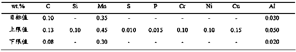
[0018] The low-carbon, low-silicon and aluminum-containing steel described in this example is ML08Al, and its C, Si, Mn, S, P, Cr, Ni, Cu and Al element content requirements are as follows:

[0019]

[0020] In this embodiment, a 120 t converter is used, the ladle is a 120 t ladle, and the ladle furnace is a 120 t ladle furnace (LF refining furnace).

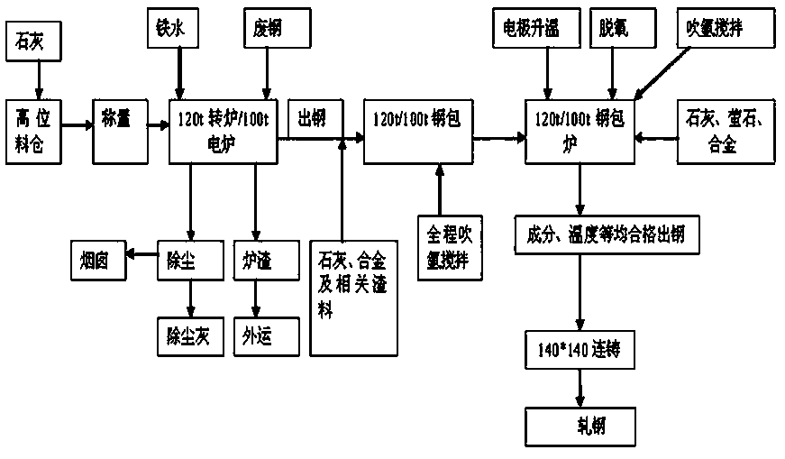
[0021] see figure 1 , Low-carbon, low-silicon and aluminum-containing steel The process before tapping the converter is: add molten iron and scrap steel to the converter, lime is sent to the converter to blow and slag after weighing through the high-level silo, and the slag is transported outside the furnace after the molten steel is tapped. The gas dust is sent into the chimney, and the particle dust is collected as dedusting ash. The molten steel adopts the method of pouring without drainage of the present invention. The specific steps of the method are as follows:

[0022] Step 1. The converter is tapped and fed. The slag...

Embodiment 2

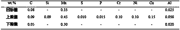
[0026] The low-carbon, low-silicon and aluminum-containing steel described in this example is SWRCH10A, and its C, Si, Mn, S, P, Cr, Ni, Cu and Al element content requirements are as follows:

[0027]

[0028] In this embodiment, a 100 t electric furnace is used, the ladle is a 100 t ladle, and the ladle furnace is a 100 t ladle furnace (LF refining furnace).

[0029] see figure 1 , Low-carbon, low-silicon and aluminum-containing steel converter before tapping process: add molten iron and steel scrap to the electric furnace, lime is sent to the electric furnace to blow and slag after weighing through the high-level silo, after the molten steel is tapped, the slag is transported outside the furnace, The gas dust is sent into the chimney, and the particle dust is collected as dedusting ash. The molten steel adopts the method of pouring without drainage of the present invention. The specific steps of the method are as follows:

[0030]Step 1. Electric furnace tapping and feed...


PUM

PropertyMeasurementUnit
Lengthaaaaaaaaaa
Lengthaaaaaaaaaa

Abstract

The invention discloses a non-drainage casting method for low-carbon low-silicon aluminum-containing steel, and belongs to the technical field of metallurgical production processes. The method comprises the following specific steps: adopting converter/electric furnace tapping liquid for casting, sequentially adding aluminum ingots, cold heading steel synthetic slag, low-carbon ferromanganese alloy, carbon powder, lime and fluorite into a steel ladle during converter/electric furnace tapping, performing bottom blowing of Ar gas to the steel ladle during tapping, and adding all alloys before tapping is finished; refining the cold heading steel, feeding a pure calcium line to carry out calcium treatment, and then blowing Ar gas to carry out soft stirring; before continuous casting, baking a tundish, blowing Ar gas into a tundish baking hole and an impact area, and adding SiCa powder or a calcium line into a tundish flow plug rod and a sizing nozzle before casting. The method disclosed bythe invention has the advantages of avoiding poor fluidity of molten steel during pouring due to impurities generated by oxidation of the molten steel, avoiding enrichment and blockage of a water gapin the pouring process, and saving energy and production cost.

Description

technical field [0001] The invention belongs to the technical field of metallurgical production technology, and in particular relates to a method for pouring low-carbon, low-silicon and aluminum-containing steel without draining. Background technique [0002] Low-carbon, low-silicon and aluminum-containing steel refers to steels with a carbon content of ≤0.25%, a silicon content of ≤0.10%, and an aluminum content of ≥0.015%. Due to low carbon, low silicon and high oxygen content in steel, this kind of steel generally adopts aluminum deoxidation process. When producing this kind of steel in billets, if the purity of molten steel and the protection of pouring process are not done well, the first step is to start pouring. During the furnace, the molten steel oxidizes to form alumina-like inclusions, which deteriorates the fluidity of the molten steel, and during the continuous casting pouring process, alumina accumulates at the nozzle of the stopper to block the nozzle, causi...

Claims


Application Information

Patent Timeline
IPC IPC(8): C21C7/00C21C7/072C22C38/42C22C38/06C22C38/04C22C38/02
CPCC21C7/0006C21C7/0056C21C7/0068C21C7/072C22C38/002C22C38/02C22C38/04C22C38/06C22C38/42
Inventor 张玉飞李解聂文金马建超王志福严云龙
Owner ZHANGJIAGANG RONGSHENG SPECIAL STEEL CO LTD
Why Eureka
Try Eureka