Roughness inductive sensor

An inductive and roughness technology, applied in the field of roughness inductive sensors, can solve the problems of insufficient measuring range, large measuring force and large measuring range of the sensor, and achieve the effect of improving the linear range, solving the sensitivity and improving the sensitivity.

Pending Publication Date: 2020-03-27
杭州铯原科技有限公司
View PDF0 Cites 2 Cited by
  • Summary
  • Abstract
  • Description
  • Claims
  • Application Information

AI Technical Summary

Problems solved by technology

[0003] At present, there are technical gaps in many high-end manufacturing processes in our country, such as high-end bearing manufacturing. In addition to design, processing, materials, heat treatment and other reasons, the more important thing is that the detection technology of surface roughness is relatively backward.
In the bearing manufacturing industry, in addition to using roughness testing tools to detect the surface roughness of the bearing, it is also necessary to measure the groove curvature of the raceway and the roughness of the inner and outer rings, and the measurement accuracy is relatively high, that is to say, the measuring tools A large measurement range is required, and both roughness and a certain profile must be taken into account at the same time. However, most domestic manufacturers of roughness testing equipment cannot meet this demand. At present, the main problems of domestic roughness sensors are:
[0004] 1. The measurement range of the sensor is not enough, the general range is within ±80μm
[0005] 2. The measuring force is large, which may easily cause the diamond stylus to scratch the surface of the workpiece to be measured, which will distort the measured data
[0006] 3. The linearity of the inductance coil is not good, and there is a large deviation at both ends of the range
[0007] 4. The support part of the lever is a difficult point. The use of shrapnel is easy to produce plastic deformation, while the use of ordinary bearings will cause a large gap when the lever is installed, which will cause a large hysteresis in the sensor
[0008] 5. The user cannot replace the stylus assembly independently, and the maintenance or overhaul is cumbersome

Method used


Image

  • Roughness inductive sensor
  • Roughness inductive sensor
  • Roughness inductive sensor

Examples


Embodiment Construction

[0034] Below in conjunction with accompanying drawing and embodiment, further elaborate the present invention. In the following detailed description, certain exemplary embodiments of the invention are described by way of illustration only. Needless to say, those skilled in the art would realize that the described embodiments can be modified in various different ways, all without departing from the spirit and scope of the present invention. Accordingly, the drawings and description are illustrative in nature and not intended to limit the scope of the claims.

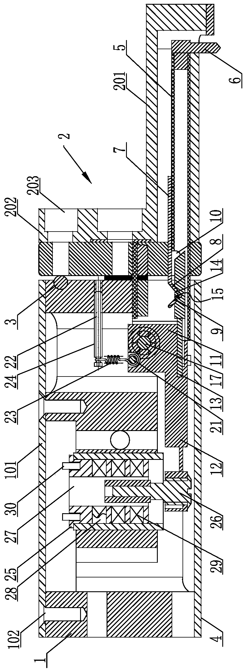
[0035] Such as figure 1 As shown, the roughness inductive sensor includes a substrate 1, the substrate 1 is configured as a cylindrical structure, and is mainly used to package internal electronic components to form a package protection structure of the sensor, and a detachable button cover 101 can be provided on the outside thereof, Utilize the cooperation of connecting bolt and bolt hole 102 ( figure 1 The connecting...


PUM


Abstract

The invention discloses a roughness inductive sensor including a substrate, one side of the substrate is detachably connected with a detection sleeve; a quick-release measuring rod device is sleeved in the detection sleeve; a magnetic core driving device mounted through a precise rotating device is arranged in the substrate; a force measurement adjusting device is further connected between the magnetic core driving device and the substrate, a coil framework and a magnetic core are further packaged in the substrate, a core hole penetrates through the coil framework, the magnetic core penetratesthrough the magnetic core driving device and extends into the core hole, a coil groove and a coil are arranged on the coil framework around the core hole, and a binding post is further arranged on the coil framework. The resolution ratio is ensured; according to the sensor, the measuring range of the sensor is increased, the sensor is more suitable for detection of a workpiece with a large-curvature surface, hysteresis of the sensor is reduced, sensitivity of the sensor is improved, adjustability of static measuring force is achieved, the problem that the surface of the detected workpiece isscratched is solved, and the structure is large in linear range, capable of being disassembled quickly and convenient to replace.

Description

technical field [0001] The invention relates to the technical field of machining product detection, in particular to a roughness inductive sensor. Background technique [0002] Surface roughness is one of the important indicators to measure whether a machined product is qualified. High-precision inductive displacement sensor is used to measure the surface roughness of the product, which has become one of the cores of precision shape measurement technology and is widely used in the machining manufacturing industry. . [0003] At present, there are technical gaps in many high-end manufacturing processes in my country, such as high-end bearing manufacturing. In addition to design, processing, materials, heat treatment and other reasons, more importantly, the detection technology of surface roughness is relatively backward. In the bearing manufacturing industry, in addition to using roughness testing tools to detect the surface roughness of the bearing, it is also necessary to ...

Claims


Application Information

Patent Timeline
Patent Type & Authority Applications(China)
IPC IPC(8): G01B7/34
CPCG01B7/34
Inventor 刘志艺王鹏伟
Owner 杭州铯原科技有限公司
Why Eureka
Try Eureka