Unit circuit for remotely detecting state of three-color lamp and implementation method

A unit circuit and remote detection technology, applied in the direction of program control, general control system, testing optical performance, etc., can solve the problems of high detection cost, time-consuming and labor-intensive, damage to equipment, etc., to achieve convenient installation, cost saving, and long-distance saving The effect of wiring

Pending Publication Date: 2020-03-27
TIANJIN ZHONGHUAN ELECTRONICS COMP
View PDF0 Cites 0 Cited by
  • Summary
  • Abstract
  • Description
  • Claims
  • Application Information

AI Technical Summary

Problems solved by technology

[0003] The state detection method of the three-color light, one requires artificial close observation, but cannot be remotely detected in real time
One is to use an instrument to detect the state of the three-color lamp. During the detection, the device needs to be disassembled, the detection instrument is connected to the three-color lamp, and the I / O level signal of the lamp is directly read to detect the state of the three-color lamp. The method needs to disassemble the device, and there is a risk of damage to the device
Another detection method is to read the state of the three-color lamp through an external sensor. Now most of the three-color lamps installed in different types of equipment in the production workshop are different, and the brightness and flickering frequency of the lamp are different, so they are different. Different models of tri-color lamps need to be equipped with different types of sensors. The disadvantages are that the detection cost is high, time-consuming and labor-intensive

Method used


Image

  • Unit circuit for remotely detecting state of three-color lamp and implementation method
  • Unit circuit for remotely detecting state of three-color lamp and implementation method
  • Unit circuit for remotely detecting state of three-color lamp and implementation method

Examples


Embodiment Construction

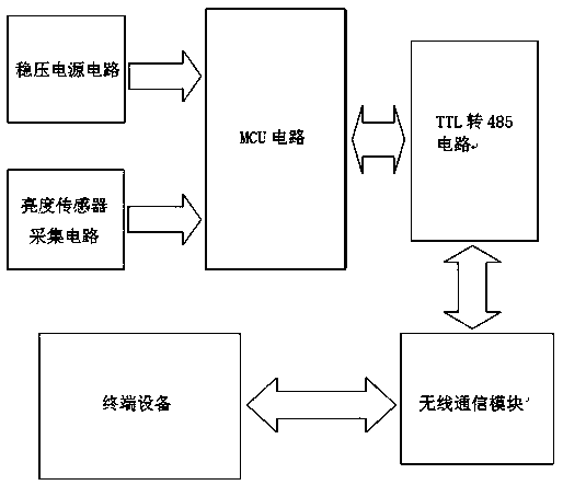
[0024] Such as Figure 1 to Figure 5 As shown, the unit circuit for remote detection of the state of the three-color light includes a brightness sensor acquisition circuit, a regulated power supply circuit, an MCU circuit, a TTL to 485 circuit, a wireless communication module, and a terminal device. The circuit, the TTL to 485 circuit, and the regulated power supply circuit are connected, the TTL to 485 circuit is connected to the terminal equipment through the wireless communication module, and the MCU circuit is provided with a processing program.

[0025] working principle:

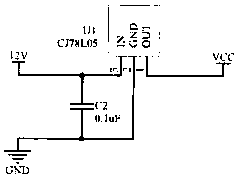
[0026] Pin 1 of CJ78L05 voltage regulator chip U1 in the power supply circuit is the power output terminal VCC, pin 2 and pin 3 are connected in parallel with capacitor C2, pin 2 is grounded to GND, pin 3 is input with 12V power supply, and the voltage is converted into 5v voltage through the voltage regulator chip U1 to give The entire circuit is powered.

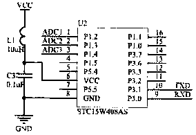
[0027] Pin 1 of the sensor interface J1 of...


PUM


Abstract

The invention discloses a unit circuit for remotely detecting the state of a three-color lamp and an implementation method. Three sensor interfaces J1, J2 and J3 of a collection unit circuit are respectively pasted on lamp posts of three colors of detected three-color lamp collection equipment through a brightness sensor; terminal equipment sends a data acquisition instruction; an MCU circuit receives an instruction through the TTL-to-485 circuit; the MCU circuit processes AD analog-to-digital conversion of the data acquired by the brightness sensor acquisition circuit; and the processed datais sent to the wireless communication module, the router and the terminal equipment in sequence through the TTL-to-485 conversion circuit, a webpage is opened on the terminal device equipment to checkthe real-time change numerical value of the three-color lamp, then whether the numerical value is within a preset threshold range or not is analyzed, and if not, the three-color lamp is in an abnormal state. The states of three-color lamps of most three-color lamp acquisition equipment on the market can be detected, the operation states of multiple devices can be monitored at the same time, costis low, and application is convenient.

Description

technical field [0001] The invention relates to a unit circuit and a realization method for remotely detecting the state of a three-color lamp, which are used for remotely detecting the state of a three-color lamp on a device and judging the operating state of the device. Background technique [0002] At present, the equipment used in industrial production, such as printing machines, assembly lines, wave soldering and other equipment, all have three-color lights to display the operating status of the equipment. By observing the bright and flashing status of the three-color lights, you can intuitively view the equipment The running state of the machine, such as abnormal shutdown, not running in standby state, prompt of material exhaustion, not running in stop state, etc. [0003] The state detection method of the three-color light, one requires artificial close observation, but cannot be remotely detected in real time. One is to use an instrument to detect the state of the t...

Claims


Application Information

Patent Timeline
Patent Type & Authority Applications(China)
IPC IPC(8): G01M11/02G05B19/042G08C17/02
CPCG01M11/02G05B19/0428G08C17/02
Inventor 张文博邢俊荣温美思丁飒李美霞苏双燕刘强
Owner TIANJIN ZHONGHUAN ELECTRONICS COMP
Why Eureka
Try Eureka