
Delivery system of liquid hydrogen refueling station and liquid hydrogen refueling station

A technology of conveying system and hydrogen refueling station, applied in the field of hydrogen refueling station, can solve the problems of long hydrogen refueling time, serious energy consumption of hydrogen refueling station, increase in temperature rise, etc., and achieve the effect of reducing refrigeration power consumption and energy consumption

Pending Publication Date: 2020-03-31
CHNA ENERGY INVESTMENT CORP LTD +1
View PDF0 Cites 3 Cited by
  • Summary
  • Abstract
  • Description
  • Claims
  • Application Information

AI Technical Summary

Problems solved by technology

The 70MPa filling hydrogen is in high-speed flow and expansion, and the temperature rises sharply. If the 35MPa filling mode is still adopted, the hydrogenation time will be very long
However, purely relying on energy such as electric energy to cool high-pressure hydrogen gas consumes a lot of electricity, and the energy consumption of hydrogen refueling stations is relatively serious.

Method used


Image

  • Delivery system of liquid hydrogen refueling station and liquid hydrogen refueling station
  • Delivery system of liquid hydrogen refueling station and liquid hydrogen refueling station
  • Delivery system of liquid hydrogen refueling station and liquid hydrogen refueling station

Examples


Embodiment Construction

[0026] The specific implementation manners of the embodiments of the present invention will be described in detail below in conjunction with the accompanying drawings. It should be understood that the specific implementation manners described here are only used to illustrate and explain the embodiments of the present invention, and are not intended to limit the embodiments of the present invention.

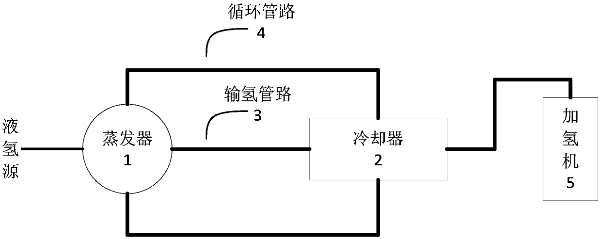
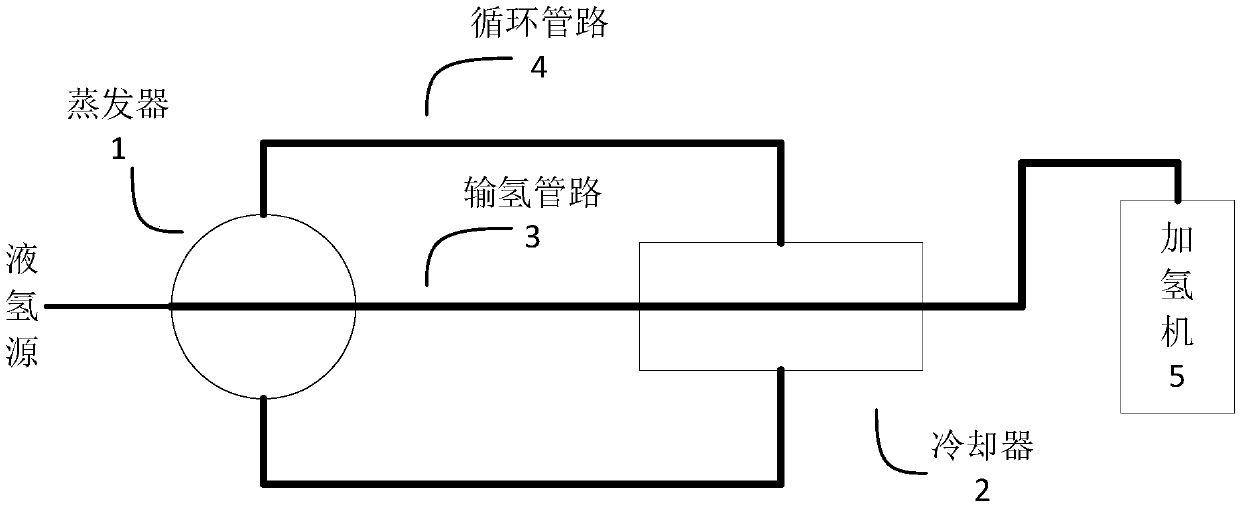
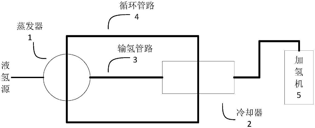
[0027] figure 1 It is a schematic structural diagram of a delivery system of a liquid hydrogen refueling station provided by an embodiment of the present invention. Such as figure 1 As shown, the hydrogenation station includes a hydrogenation machine 5, and the system includes: an evaporator 1, a cooler 2, a hydrogen pipeline 3 and a circulation pipeline 4, wherein the evaporator 1 passes through the hydrogen pipeline 3 Connect the liquid hydrogen provided by the liquid hydrogen source, and the liquid hydrogen is vaporized in the evaporator 1; the cooler 2 is connected to the hy...


PUM


Abstract

The embodiment of the invention provides a delivery system of a liquid hydrogen refueling station and the hydrogen refueling station, and belongs to the field of hydrogen refueling stations. The hydrogen refueling station comprises a hydrogen refueling machine. The delivery system comprises an evaporator, a cooler, hydrogen delivery pipelines and circulating pipelines; the evaporator is connectedwith liquid hydrogen supplied by a liquid hydrogen source through the corresponding hydrogen delivery pipeline, and the liquid hydrogen is vaporized in the evaporator; the cooler is connected betweenthe hydrogen refueling machine and the evaporator through the corresponding hydrogen delivery pipelines and used for cooling the vaporized liquid hydrogen; and the circulating pipelines are arranged between the evaporator and the cooler and are independent of the hydrogen delivery pipelines in terms of the connectivity, heat exchange media are contained in the circulating pipelines, and then the heat exchange media circulate between the evaporator and the cooler to achieve heat exchange with the liquid hydrogen in the evaporator and achieve heat exchange with the vaporized liquid hydrogen in the cooler. According to the delivery system of the liquid hydrogen refueling station and the liquid hydrogen refueling station, energy consumption of the hydrogen refueling station can be reduced.

Description

technical field [0001] The invention relates to a hydrogen refueling station, in particular to a delivery system of a liquid hydrogen refueling station and a liquid hydrogen refueling station. Background technique [0002] Hydrogen is refueled for fuel cell vehicles through a hydrogenation machine at a hydrogenation station, and stored in a vehicle-mounted hydrogen cylinder in a high-pressure form. The mainstream storage pressure is divided into two types: 35MPa and 70MPa. [0003] The high-pressure hydrogen expands in the hydrogen storage bottle, and due to the scorching effect of hydrogen, the temperature inside the bottle rises. Due to the fast filling speed, the vehicle-mounted hydrogen storage bottle cannot dissipate heat in time, causing the temperature inside the hydrogen storage bottle to rise rapidly, which may exceed the current international standard of 85°C, posing a great safety hazard. The temperature rise of the hydrogenation process with a pressure level of ...

Claims


Application Information

Patent Timeline
Patent Type & Authority Applications(China)
IPC IPC(8): F17C7/04F17C13/00
CPCF17C7/04F17C13/00F17C2221/012F17C2223/013F17C2225/0123F17C2227/0302F17C2227/0337F17C2227/0365F17C2227/039F17C2227/0393F17C2265/068F17C2265/061Y02E60/32
Inventor 许壮杨康赵月晶范玉建
Owner CHNA ENERGY INVESTMENT CORP LTD
Learn More