Method for automatically generating scanning area in CT system

A scanning area and automatic generation technology, which is applied in the field of medical imaging, can solve the problems of inaccurate scanning area, increased workload of scanning technicians, and long time, so as to achieve the effect of reducing workload, shortening preparation time, and improving preparation time

Active Publication Date: 2020-03-31
NANJING ANKE MEDICAL TECH CO LTD
View PDF4 Cites 1 Cited by
  • Summary
  • Abstract
  • Description
  • Claims
  • Application Information

AI Technical Summary

Problems solved by technology

[0004] 1. The scanning technician needs to manually select the scanning area, which increases the workload of the scanning technician
[0005] 2. The position of the scanning area will be artificially affected, which may cause the problem that the selected scanning area is inaccurate
[0006] 3. It takes a long time from the scan positioning phase until the scan technician selects the scan area. If the patient moves during this process, the selected scan area will be inaccurate.

Method used


Image

  • Method for automatically generating scanning area in CT system
  • Method for automatically generating scanning area in CT system
  • Method for automatically generating scanning area in CT system

Examples


Embodiment 1

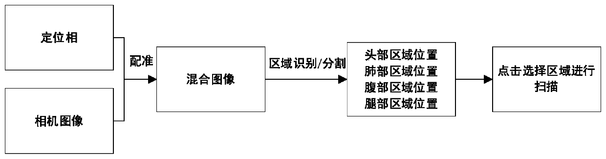
[0046] Embodiment 1: In this embodiment, a camera installed directly above the CT bed is used to collect images of patients on the bed. When collecting images, the camera shoots vertically downward, and the collected images are sent to the computer system of the CT system for image analysis and processing. .

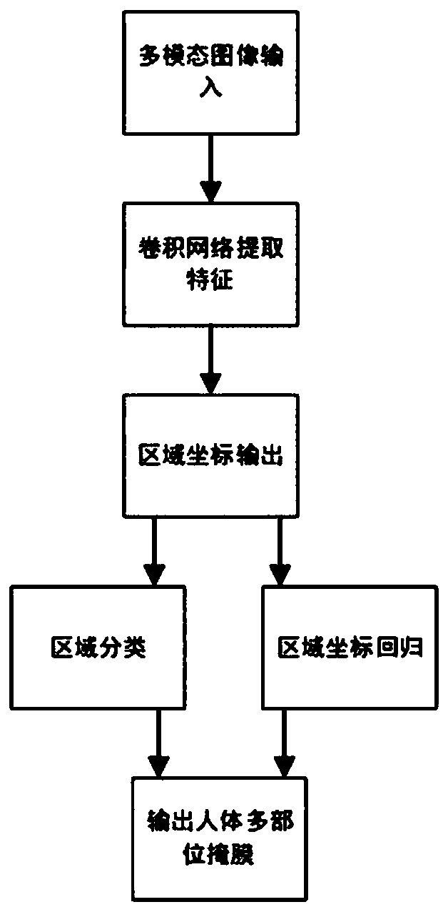
[0047] In this embodiment, the target detection model based on the convolutional neural network is used to process the input image, and the target detection model based on the convolutional neural network is an RCNN structure, such as image 3 As shown, it includes a candidate region extraction network, a CNN feature extractor, a classifier and a regressor; the candidate region extraction network generates a candidate frame according to the input image and adjusts the size of the candidate frame to a specified size, and the CNN feature extractor extracts each The feature vector of the candidate frame, the extracted feature vector is sent to the classifier for classificat...

Embodiment 2

[0059] Embodiment 2: In this embodiment, a camera installed directly above the CT bed is used to collect images of patients on the bed. When collecting images, the camera shoots vertically downward, and the collected images are sent to the computer system of the CT system for image analysis and processing. .

[0060] In this embodiment, the image segmentation model based on the convolutional neural network is used to process the input image, and the image segmentation model based on the convolutional neural network is a UNet structure, such as Figure 4 As shown, it includes: an input module, a feature extraction module, an upsampling module and an output module, wherein the input module inputs multimodal image data (CT positioning phase data and images taken by the camera are registered and cropped to the same size image data) , the feature extraction module consists of cascaded convolution and pooling operations to extract input features; the upsampling module consists of up...


PUM


Abstract

The invention provides a method for automatically generating a scanning area in a CT system. According to the method, firstly, images of patients on a CT sickbed are collected in real time, then scanning area rapid extraction and classification are conducted on the collected images through a pre-trained scanning area segmentation model, and an operator only needs to select an area needing to be scanned to control a CT system to scan the selected area. According to the invention, the workload of operators is fully reduced, inaccurate scanning area selection caused by human subjective factors can be avoided, the preparation time before scanning is shortened, and low scanning data accuracy caused by the fact that a patient difficultly keeps a specified scanning posture due to too long waitingtime is avoided.

Description

technical field [0001] The invention relates to the technical field of medical imaging, in particular to a method for automatically generating scanning regions in a CT system. Background technique [0002] Usually CT (Computed Tomography, electronic computer tomography) needs to scan the positioning phase before scanning the patient, and then the doctor selects the position and protocol to be scanned in the positioning phase view interface, and the scanning software pops up the default scan according to the scanning part and protocol selected by the doctor area rectangle. Finally, the doctor needs to manually drag the rectangular frame of the scanning area and adjust the size of the rectangular frame according to the specific conditions of each patient. Because different patients have great differences in height and body shape, doctors need to spend more time adjusting the scanning area frame, and this repeated adjustment process increases the doctor's considerable workload...

Claims


Application Information

Patent Timeline
Patent Type & Authority Applications(China)
IPC IPC(8): G06T11/00G06T7/33G06T7/11
CPCG06T11/005G06T7/33G06T7/11G06T2207/10081G06T2207/20081G06T2207/20084G06T2207/20132
Inventor 曾凯傅鹏
Owner NANJING ANKE MEDICAL TECH CO LTD
Why Eureka
Try Eureka