Cross-scale double-band-pass frequency selective surface and periodic unit and design method thereof

A frequency-selective surface and dual-bandpass technology, which is applied in the field of stealth technology and radome, can solve problems such as difficult to stabilize filtering, and achieve the effect of improving the wave transmission rate

Active Publication Date: 2020-03-31
CHANGCHUN INST OF OPTICS FINE MECHANICS & PHYSICS CHINESE ACAD OF SCI
View PDF10 Cites 11 Cited by
  • Summary
  • Abstract
  • Description
  • Claims
  • Application Information

AI Technical Summary

Problems solved by technology

[0009] The purpose of the present invention is to provide a cross-scale dual-band-pass frequency selective surface, its periodic unit, and a design method, aiming at solving the problem of cross-scale dual-band-pass frequency selective surface under wide-angle (0°~50°) irradiation in the prior art. The technical problem that the two passbands are difficult to filter stably

Method used


Image

  • Cross-scale double-band-pass frequency selective surface and periodic unit and design method thereof
  • Cross-scale double-band-pass frequency selective surface and periodic unit and design method thereof
  • Cross-scale double-band-pass frequency selective surface and periodic unit and design method thereof

Examples


Embodiment 1

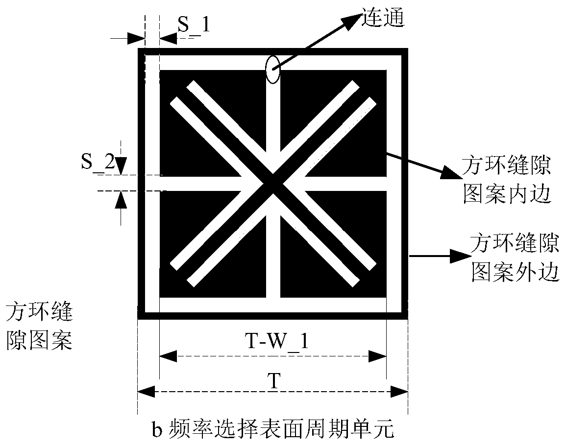
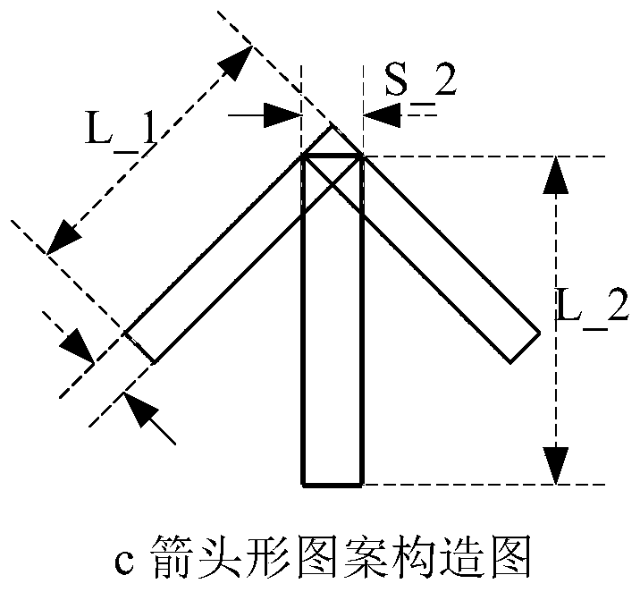
[0036] figure 1 A schematic diagram showing the periodic unit of the cross-scale dual-bandpass frequency selective surface provided by this embodiment. Such as figure 1 As shown, the periodic unit of the cross-scale dual-bandpass frequency selective surface provided by this embodiment includes a square annular slot patch and an arrow-shaped slot patch, and the gap between the square annular slot patch and the arrow-shaped slot patch is connected. .

[0037] The square annular slit patch is connected to the slit of the arrow-shaped slit patch to obtain a cross-scale double-bandpass frequency selective surface.

[0038] According to the principle of FSS electromagnetic resonance, when the wavelength is consistent with the size of the gap structure, the strongest electromagnetic resonance is generated and a passband is formed.

[0039] The size of the square annular slot patch is determined by the center frequency and bandwidth of the first passband in the unit, and the size o...

Embodiment 2

[0050] Figure 4 It is a schematic diagram of the cross-scale dual-bandpass frequency selective surface shown in Embodiment 2. The cross-scale dual-bandpass frequency selective surface shown in the second embodiment includes an array composed of 3×3 periodic units as described in the first embodiment.

[0051] Optionally, the cross-scale dual-bandpass frequency selective surface may also be other types of arrays composed of the periodic units as described in Embodiment 1, which will not be described here.

[0052] Optionally, the cross-scale dual-bandpass frequency selective surface is fixed on a support medium, and the support medium is a polyimide film. For example, the supporting medium is a polyimide film with a thickness of 0.025mm, its relative permittivity εr=3, and its loss tangent tanδ=0.005.

Embodiment 3

[0054] Figure 5 It is a flowchart for realizing the design method of the cross-scale dual-bandpass frequency selective surface shown in the third embodiment. Through the flow chart of the design method of the cross-scale dual-band-pass frequency selective surface shown in the third embodiment, the design of the periodic unit as described in the first embodiment and the design of the cross-scale dual-band-pass frequency selective surface as described in the second embodiment is carried out. For ease of description, only the parts related to the embodiments of the present invention are shown, and the details are as follows:

[0055] Step S110, establishing a periodic unit of a cross-scale dual-bandpass frequency selective surface;

[0056] Step S120, loading a supporting medium on one side of the periodic unit;

[0057] In step S130, the periodical unit and the support medium are first topologically arranged along the x-axis direction, and then the topological structure is to...


PUM


Abstract

The invention is applicable to the technical field of stealth technologies and radar radomes, and provides a periodic unit of a cross-scale double-band-pass frequency selective surface, the periodic unit comprises a square annular slot patch and an arrow-shaped slot patch, and the square annular slot patch is communicated with a slot of the arrow-shaped slot patch. A periodic unit of a cross-scaledouble-band-pass frequency selective surface is designed by adopting a novel composite FSS pattern; according to the dual-waveband wave-transparent radome, the wave-transparent rates, bandwidths, angles and polarization stability of two passbands can be improved, high wave-transparent performance of two working wavebands of the dual-waveband wave-transparent radome under the non-frequency-doubling relation can be guaranteed, and the wave-transparent and stealth requirements can still be met under wide-angle (0-50 degrees) irradiation.

Description

technical field [0001] The invention belongs to the field of stealth technology and radome technology, and in particular relates to a cross-scale dual-bandpass frequency selective surface, a periodic unit and a design method thereof. Background technique [0002] With the development of military technology, it is required to further improve the strike range of aircraft and the level of precision guidance. This puts forward the requirement of wide-band wave penetration for the key component of aircraft, radome. It requires accurate capture and tracking of targets in a wide range. It not only improves the hit accuracy, but also reduces the technical difficulty of anti-shutdown and the requirements for airborne target positioning equipment. [0003] Modern battlefield electronic countermeasures are becoming more and more complex, and weapons and equipment guided by a single system will be seriously threatened. Using multi-mode compound homing guidance and making full use of the...

Claims


Application Information

Patent Timeline
Patent Type & Authority Applications(China)
IPC IPC(8): H01Q15/00H01Q1/42
CPCH01Q1/42H01Q15/0013H01Q15/0046
Inventor 徐念喜高劲松单冬至宋乃涛陈新
Owner CHANGCHUN INST OF OPTICS FINE MECHANICS & PHYSICS CHINESE ACAD OF SCI
Why Eureka
Try Eureka