
Wiring terminal connecting structure and processing method thereof

A technology of terminal and connection structure, applied in the direction of connection, connection insulation, conductive connection, etc., can solve the problems of complex processing, large diameter of the cable at the connection, low reliability, etc., to achieve reliable connection structure, ensure processing quality, improve The effect of reliability

Active Publication Date: 2020-03-31
BEIJING HANGXING MACHINERY MFG CO LTD
View PDF3 Cites 0 Cited by
  • Summary
  • Abstract
  • Description
  • Claims
  • Application Information

AI Technical Summary

Problems solved by technology

[0005] In view of the above analysis, the present invention aims to provide a terminal connection structure and its processing method to solve the problems of low reliability, complicated processing and large cable diameter at the connection point of the existing terminal

Method used


Image

  • Wiring terminal connecting structure and processing method thereof
  • Wiring terminal connecting structure and processing method thereof

Examples


Embodiment 1

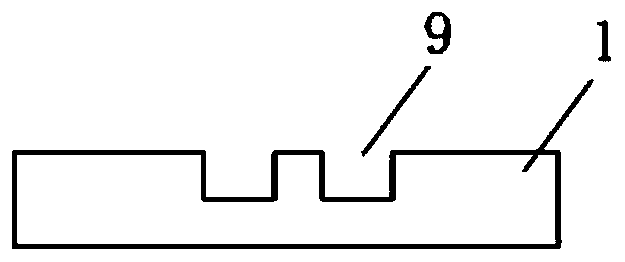
[0038] A specific embodiment of the present invention discloses a connection structure of a terminal, such as Figure 1 to Figure 2 As shown, it includes terminal 1, terminal heat-shrinkable tube 2, wire shielding inner protective heat-shrinkable tube 3, wire shielding layer 4, and shielded heat-shrinkable tube 5; among them, terminal 1 has a cavity structure, and the wiring The cavity of the terminal 1 is for the core wire 7 of the wire to be connected to penetrate. The wire to be connected is sequentially sheathed with a wire shielding layer inner protective heat shrinkable tube 3 and a wire shielding layer 4, that is, the wire core 7 is a wire insulation layer 8 and a wire shielding layer inner protective heat shrinkable tube 3 from the inside to the outside. The distance between the wire shielding layer 4, the wire insulation layer 8, the protective heat shrinkable sleeve 3, the wire shielding layer 4 and the end surface of the terminal 1 increases in turn, and the optical ...

Embodiment 2

[0054] Another specific embodiment of the present invention discloses the processing method of the connection terminal connection structure in embodiment 1, which specifically includes the following steps:

[0055] Step 1: Disconnect the ends of the two wires to be connected to leak the wire core 7; insert the leaked wire core 7 into the internal cavity of the terminal 1, and observe whether the wire core 7 is in place through the observation hole 9 . Among them, the stripping length, that is, the length of the insulation layer of the hot stripping wire end is A+B+C. The wire after the end treatment should be guaranteed to be free of damage, no broken wires, no residues, and no Rust and no loose wire.

[0056] Step 2: Put the terminal heat shrinkable tube 2 on the terminal 1, make the terminal heat shrinkable tube 2 wrap around the terminal 1 and the wire insulation layer 8 on both sides of the terminal 1, and connect the terminal heat shrinkable tube 2 Perform heat shrinkage tre...


PUM


Abstract

The invention relates to a wiring terminal connecting structure and a processing method thereof, belongs to the technical field of electric fittings, and solves the problems that an existing wiring terminal is poor in reliability, complex in processing and large in cable diameter at the joint. A wiring terminal connecting structure comprises a wiring terminal, a wiring terminal heat-shrinkable sleeve, a wire shielding layer inner protection heat-shrinkable sleeve, a wire shielding layer and a shielding heat-shrinkable sleeve. A wire core wire of a wire to be connected sequentially comprises awire insulating layer, a wire shielding layer inner protection heat-shrinkable sleeve and a wire shielding layer from inside to outside. The wiring terminal heat-shrinkable sleeve is sleeved outside the wiring terminal and envelops the wire insulating layers at the two ends of the wiring terminal; and the shielding heat-shrinkable sleeve is sleeved outside the wiring terminal heat-shrinkable sleeve and envelops the sleeving length of the wire shielding layers at the two ends of the wiring terminal. The device is simple in structure, high in reliability, simple in processing technology, easy toprocess and small in cable diameter at the joint.

Description

Technical field [0001] The present invention relates to the technical field of electrical equipment, in particular to a connection terminal connection structure and a processing method thereof. Background technique [0002] In the current cable design process, due to voltage attenuation requirements, wires with larger diameters are often selected to reduce voltage loss, while redundant design requirements often require multiple wires to be processed at the same terminal. Due to the limitation of the characteristics of the cable network connector, it is often necessary to use the terminal block for wire connection, and the continuity of the shielding layer at both ends of the terminal block is very important. [0003] At present, the methods frequently used to deal with the continuity of shielded conductors are: shielding cross-line, wave-breaker envelope and other methods. The shielding cross-line processing method is simple and low-cost, but its shielding effect is poor, which is...

Claims


Application Information

Patent Timeline
IPC IPC(8): H01R11/01H01R11/09H01R4/72H01R43/00
CPCH01R4/72H01R11/01H01R11/09H01R43/00
Inventor 孙风杰张卫娟郝景洋韩宁于雪伦郭晓敏廖彦贝王国英王岳
Owner BEIJING HANGXING MACHINERY MFG CO LTD
Learn More