Shield tail grouting liquid mixing valve

A grouting and liquid mixing technology, applied in mining equipment, earthwork drilling, tunnels, etc., can solve the problems of complex structure and inconvenient construction operation, and achieve the effect of simplifying steps and reducing workload

Pending Publication Date: 2020-04-03
CHINA RAILWAY 14TH BUREAU GRP LARGE SHIELD ENG CO LTD
View PDF0 Cites 0 Cited by
  • Summary
  • Abstract
  • Description
  • Claims
  • Application Information

AI Technical Summary

Problems solved by technology

[0004] The entire shield machine is composed of tens of thousands of parts. The structure of the entire shield equipment is complex and powerful, so most of the accessories have corresponding functions and functions. Among them, grouting to the tail of the shield is a part of the work of the shield machine. The common procedure is to inject mud into the tunnel segment. The shield tail grouting operation requires the use of multiple accessories, and the grouting port seal is one of the common accessories. The existing seals mainly include mounting blocks, embedded Composed of block and sealing groove, the embedded block and sealing groove are used for sealing, the installation block is used for fixing, and the seal is used to seal the grouting port. When grouting, the seal is removed, and the grouting is completed. The seal is fixed well. Although the seal can play an effective sealing role, the shield tail grouting needs to be grouted at multiple grouting ports. Therefore, the seal needs to be continuously disassembled and installed during the grouting process. The operation brings inconvenience. Therefore, the present invention proposes a shield tail grouting mixed liquid valve. By improving the structure of the existing grouting port seal, the seal has the function of grouting, which can reduce the difficulty of shield tail grouting work.

Method used


Image

  • Shield tail grouting liquid mixing valve
  • Shield tail grouting liquid mixing valve
  • Shield tail grouting liquid mixing valve

Examples


Embodiment

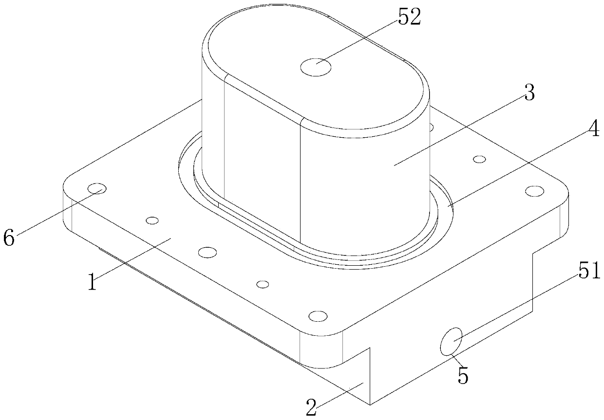
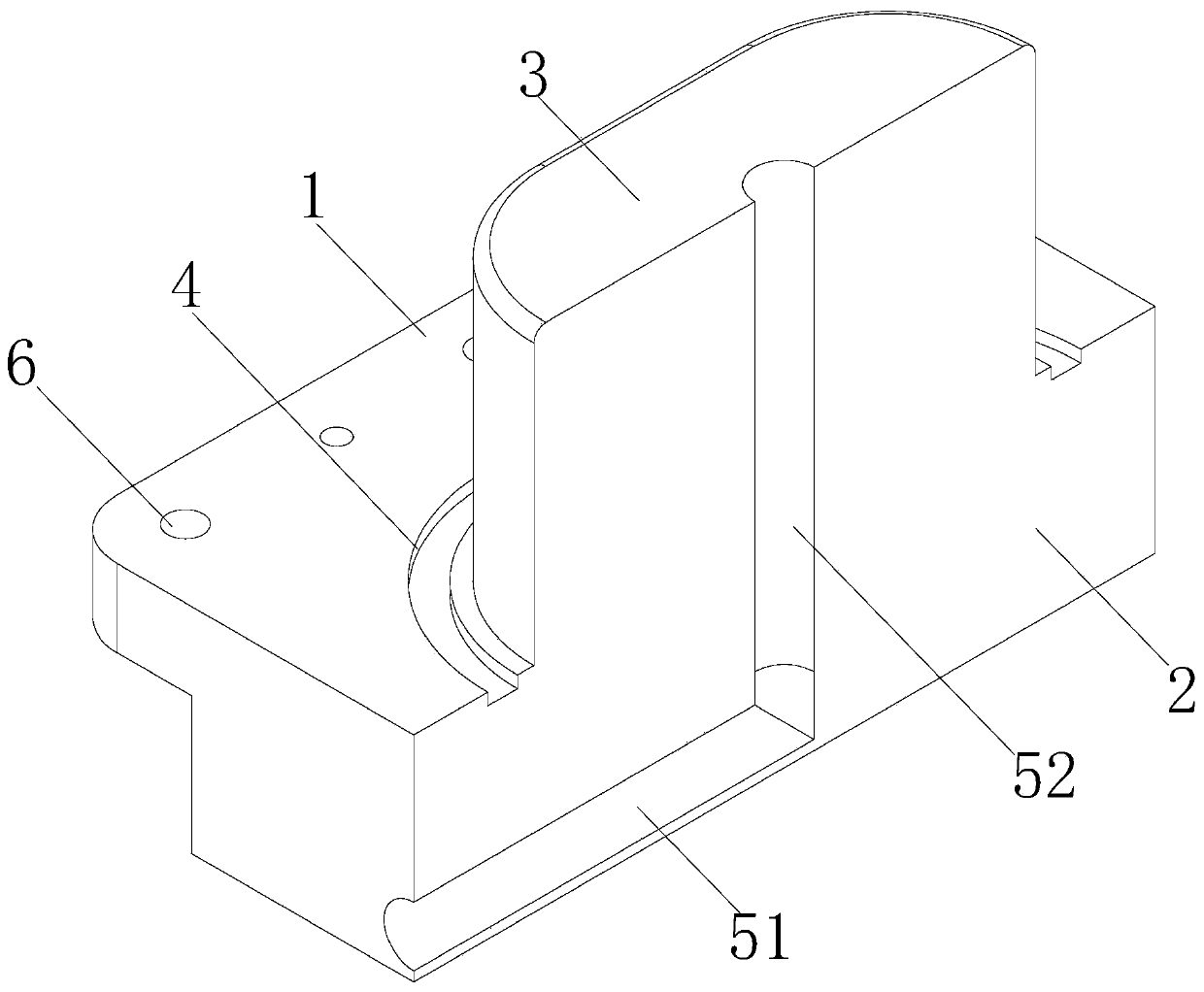
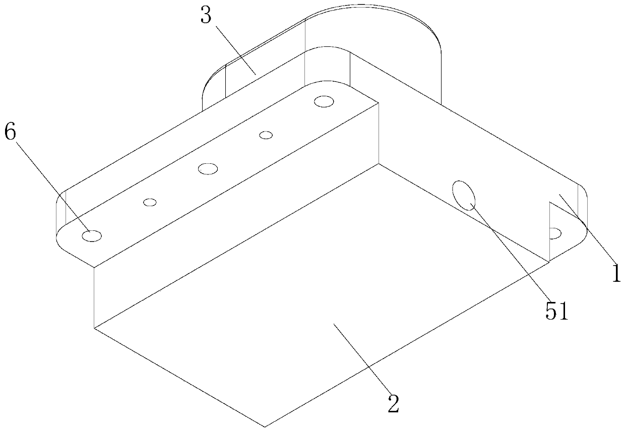
[0019] see Figure 1-3 , the present invention provides the following technical solutions: a shield tail grouting mixed liquid valve, including a mounting block 1, the bottom of the mounting block 1 is fixedly installed with a protruding block 2, the thickness of the protruding block 2 is 23cm, and the bottom of the mounting block 1 is fixed There is an embedded block 3, and a sealing groove 4 is provided on the top of the mounting block 1. The width of the sealing groove 4 is 5 cm, and the thickness of the sealing groove 4 is 2 cm. The grouting channel 5, the grouting channel 5 includes a slurry inlet channel 51 and a slurry outlet channel 52, the slurry inlet channel 51 is set in the inside of the protruding block 2 and runs through one side of the protruding block 2, and the grouting channel 52 is opened on the mounting block 1. Inside the protruding block 2 and the inner block 3 , one end of the pulp outlet channel 52 communicates with the pulp inlet channel 51 , and one e...


PUM

PropertyMeasurementUnit
Thicknessaaaaaaaaaa
Widthaaaaaaaaaa
Thicknessaaaaaaaaaa

Abstract

The invention belongs to the technical field of accessories of shield equipment and particularly relates to a shield tail grouting liquid mixing valve which comprises a mounting block, wherein a protruding block is fixedly mounted at the bottom of the mounting block and has a thickness of 23 cm; an embedded block is fixed at the bottom of the mounting block; a sealing groove is formed in the top of the mounting block, has a width of 5 cm and has a thickness of 2 cm; and a grouting passage is formed among the mounting block, the protruding block and the embedded block. According to the shield tail grouting liquid mixing valve, the structure of a sealing element of the existing grouting opening is improved; the protruding block and the grouting passage are additionally arranged on the basisof the original structure; after the mounting block is fixed, the embedded block is matched with the sealing groove to seal the grouting opening; due to existence of the grouting passage, a grout feeding passage and a grout discharging passage enable the grouting opening to communicate with the external world, and a pipeline directly communicates with the grout feeding passage for grouting operation, so that the step of shield tail grouting operation is simplified, fast shield tail grouting is facilitated, and the workload is reduced.

Description

technical field [0001] The invention relates to the technical field of shield equipment accessories, in particular to a shield tail grouting mixing liquid valve. Background technique [0002] The construction method of shield tunneling is a construction method that constructs (lays) supporting segments at the same time in the process of excavating the tunnel. The tunnel construction using shield tunneling machinery has the advantages of high automation, manpower saving, fast construction speed, one-time hole formation, It is not affected by the climate, and the ground subsidence can be controlled during construction. It is the preferred method for tunnel excavation at present. [0003] Shield construction requires the use of a shield machine, a shield machine, the full name of which is a tunnel boring machine. It is a special construction machine for tunneling. Integrating information technology, it has the functions of excavating and cutting soil, transporting soil muck, a...

Claims


Application Information

Patent Timeline
IPC IPC(8): E21D9/06
CPCE21D9/06E21D9/0607
Inventor 薛永超白坤李海振赵国栋田兆平董冰杨青林孙警娄瑞王硕
Owner CHINA RAILWAY 14TH BUREAU GRP LARGE SHIELD ENG CO LTD
Why Eureka
Try Eureka