Roller kiln

A roller kiln and kiln body technology, applied in the kiln field, can solve the problems of reducing production efficiency and shortening kiln production time, and achieve the effects of improving production efficiency, easy promotion and use, and simple structure

Pending Publication Date: 2020-04-03
FOSHAN TIANLU INTELLIGENT EQUIP TECH CO LTD
View PDF0 Cites 1 Cited by
  • Summary
  • Abstract
  • Description
  • Claims
  • Application Information

AI Technical Summary

Problems solved by technology

However, the existing roller kilns on the market only unilaterally exhaust the kiln in terms of coke discharge, and have not taken effective measures to prevent the tar volatilized from the product during the sintering process from adhering to the inner wall of the kiln. As a result, a large amount of tar sticks on the kiln wall, causing the heating rod and the roller rod to be connected by tar to produce a short-circuit discharge phenomenon, which breaks the roller rod; on the other hand, when a large amount of tar is stuck in the kiln, the current treatment method is to arrange several During this period, the kiln cannot feed materials, so that the high temperature of the kiln can decompose the tar stuck on the inner wall of the kiln, heating rods, rollers, etc., so as to reduce the occurrence of short-circuit discharge and breakage of the rollers However, this shortens the production time of the kiln accordingly and reduces the production efficiency

Method used


Image

  • Roller kiln
  • Roller kiln

Examples


Embodiment Construction

[0019] The specific implementation manners of the present invention will be further described in detail below in conjunction with the accompanying drawings and embodiments. The following examples are used to illustrate the present invention, but are not intended to limit the scope of the present invention.

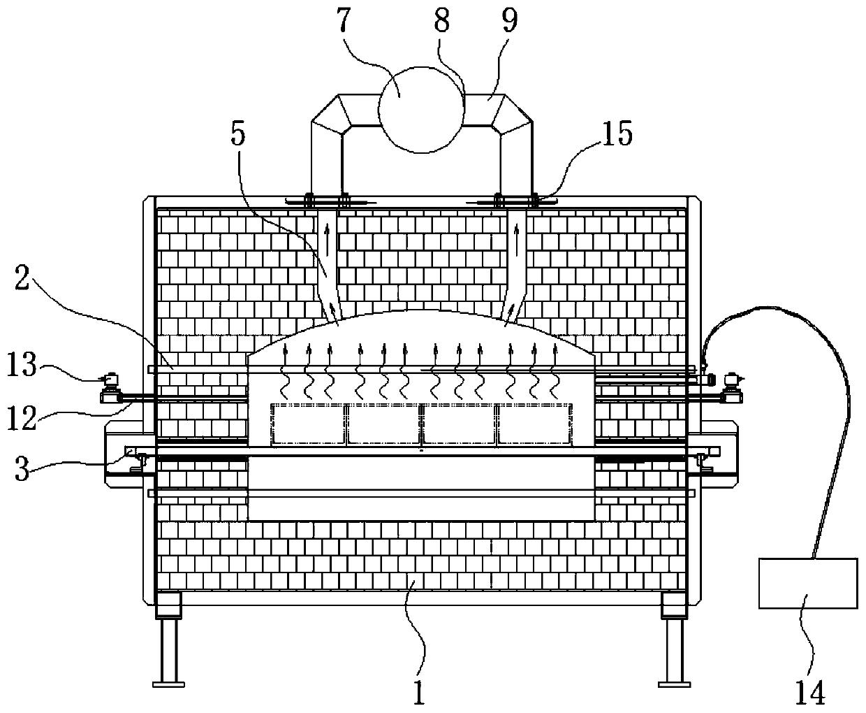
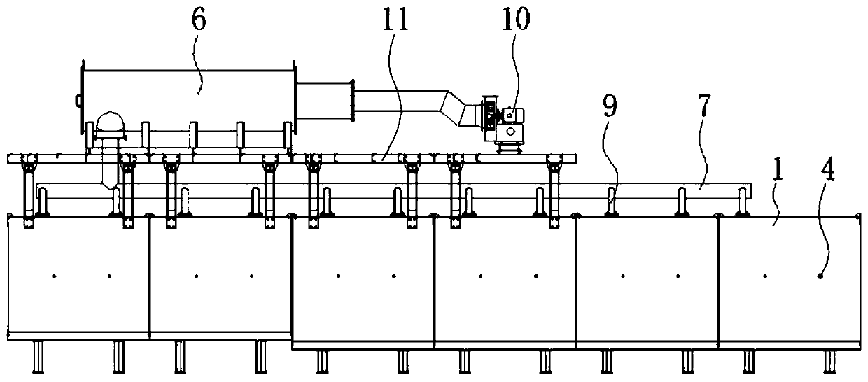
[0020] like Figure 1-2 As shown, a roller kiln according to a preferred embodiment of the embodiment of the present invention includes a kiln body 1, a heating rod 2 and a roller rod 3 for conveying materials are arranged inside the kiln body 1, and the side of the kiln body 1 The wall is provided with a number of air intake holes 4 connected to the kiln body cavity, and the top of the kiln body 1 is provided with a number of exhaust holes 5 connected to the kiln body cavity, and the gas outlet end of the exhaust holes 5 is connected with a waste gas treatment device 6 . Wherein, the exhaust gas treatment device is a prior art, which will not be introduced here.

[0021...


PUM


Abstract

The invention relates to the technical field of kilns, and discloses a roller kiln. The roller kiln comprises a kiln body, wherein a heating rod and a roller rod used for conveying materials are arranged in the kiln body, a plurality of air inlet holes communicated with an inner cavity of the kiln body are formed in the side wall of the kiln body, a plurality of exhaust holes communicated with theinner cavity of the kiln body are formed in the top of the kiln body, and the air outlet ends of the exhaust holes communicate with a waste gas treatment device. According to the roller kiln, the airinlet holes are formed in the side wall of the kiln body for conveying compressed air into the inner cavity of the kiln body, the exhaust holes are formed in the top of the kiln body, the exhaust holes communicate with the waste gas treatment device; and part of the generated tar is combusted in the inner cavity of the kiln body, and the flue gas generated by combustion and the unburned tar are blown to the inner cavity of the kiln body, enter the waste gas treatment device through the exhaust holes to be decomposed, and are then discharged to the outside, so that the tar flue gas is prevented from sticking to the kiln wall, the situation that short-circuit discharging is generated on the heating rod and the roller rod is avoided, and the roller rod is prevented from being broken. Meanwhile, due to the fact that the tar is not bonded in the kiln, there is no need to burn and discharge tar, and the production efficiency is improved.

Description

technical field [0001] The invention relates to the technical field of kilns, in particular to a roller hearth kiln. Background technique [0002] Lithium battery powder materials will volatilize a large amount of tar during high-temperature sintering, especially lithium battery negative electrode materials, which volatilize more tar. However, the existing roller kilns on the market only unilaterally exhaust the kiln in terms of coke discharge, and have not taken effective measures to prevent the tar volatilized from the product during the sintering process from adhering to the inner wall of the kiln. As a result, a large amount of tar sticks on the kiln wall, causing the heating rod and the roller rod to be connected by tar to produce a short-circuit discharge phenomenon, which breaks the roller rod; on the other hand, when a large amount of tar is stuck in the kiln, the current treatment method is to arrange several During this period, the kiln cannot feed materials, so t...

Claims


Application Information

Patent Timeline
Patent Type & Authority Applications(China)
IPC IPC(8): F27B9/04F27B9/30F27B9/40F27D7/06F27D17/00
CPCF27B9/047F27B9/30F27B9/40F27D7/06F27D17/008F27D2007/063
Inventor 不公告发明人
Owner FOSHAN TIANLU INTELLIGENT EQUIP TECH CO LTD
Why Eureka
Try Eureka