Return-to-zero control system and return-to-zero control method

A control system and host control technology, applied in the field of zeroing, can solve the problems of inability to return to zero with mechanical action, low noise, etc., and achieve the effect of reducing message delay and freeing up the processor time of the host

Active Publication Date: 2020-04-03
郑州海为电子科技有限公司
View PDF10 Cites 0 Cited by
  • Summary
  • Abstract
  • Description
  • Claims
  • Application Information

AI Technical Summary

Problems solved by technology

The amplifier adopts a one-stage folded cascode structure with differential input, which overcomes the disadvantage that the Miller compensation capacitor used in the traditional two-stage amplifier is easy to cause oscillation at a low temperature of 77K; It can work normally, and the noise is lower than the traditional circuit. This zeroing circuit is suitable for the readout of the medium-wave linear infrared HgCdTe detector signal with large non-uniformity, and it cannot perform zeroing operation for mechanical actions.

Method used


Image

  • Return-to-zero control system and return-to-zero control method
  • Return-to-zero control system and return-to-zero control method
  • Return-to-zero control system and return-to-zero control method

Examples


Embodiment 1

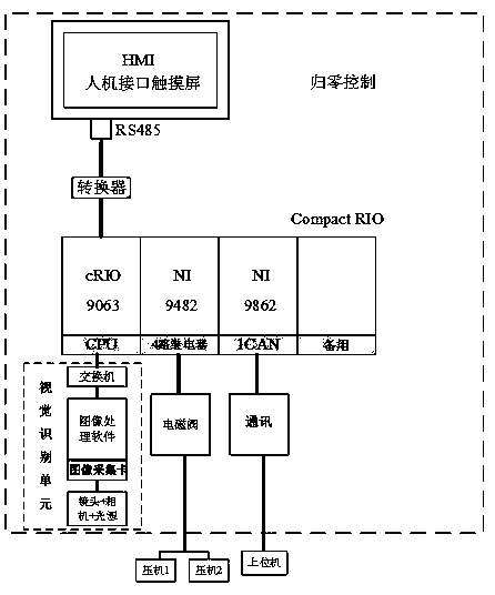
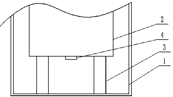
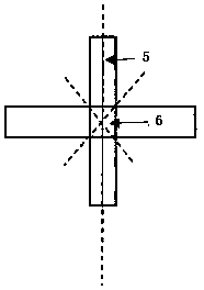
[0034] Such as figure 1 Shown is a schematic structural diagram of a zero-return control system, which is suitable for the detection and zero-return control of the deflection of the equipment itself. The outer cylinder 1, the outer cylinder 1 is fixed on the ground to keep relatively static, the inner cylinder 2 is located in the outer cylinder 1 and elastically supported by the slip ring 3, and the slip ring 3 can move along the outer cylinder in the horizontal direction translation and rotation, such as figure 2 As shown, the zeroing control system includes a control unit for controlling the press to move the inner cylinder to the initial position, a visual recognition unit for real-time measurement of the horizontal and angular displacement of the inner cylinder, and a control unit for issuing manipulation commands to the control unit PC.

[0035] The control unit includes a control host, and the control host is a CompactRIO host. The control host includes a CPU module,...

Embodiment 2

[0049] The difference between this embodiment and Embodiment 1 is that the sliding ring push function is realized by controlling the two return-to-zero presses respectively as press 1 and press 2, such as figure 1 As shown, the two zero-return presses are arranged at 180 degrees, and each press can be independently controlled to complete the rotation and locking action of the zero-return press. The specific action is: the initial state of the zero-return press is the locked state before receiving the command , the upper computer sends an unlock command, and presses 1 and 2 are unlocked. Each press has an oil inlet solenoid valve and a reverse oil inlet solenoid valve, which are used to push the presses to work in different directions. Open or close different solenoid valves according to the instructions issued by the host computer. Specifically, open the oil inlet solenoid valves of presses 1 and 2 at the same time to complete the counterclockwise rotation of the inner cylinde...


PUM


Abstract

The invention belongs to the technical field of return-to-zero control, and particularly relates to a return-to-zero control system and a return-to-zero control method which are suitable for detectingthe own deflection of a device. The return-to-zero control system is suitable for the detection and return-to-zero control of the own deflection of the device. The device comprises a pressing machinefor providing power for an inner cylinder, the inner cylinder and an outer cylinder for supporting the inner cylinder, the outer cylinder is fixed on the ground and is kept relatively static, the inner cylinder is positioned in the outer cylinder and is elastically supported by a slip ring, and the slip ring can translate and rotate along the outer cylinder in the horizontal direction. The return-to-zero control system comprises a control unit for controlling the pressing machine to move the inner cylinder to an initial position, a visual identification unit for measuring the horizontal and angular displacement of the inner cylinder in real time, and an upper computer for sending a control command to the control unit. According to the present invention, the horizontal displacement precision required by device can be 0.2 mm, and the angular displacement precision required by the device can be 50 ''.

Description

technical field [0001] The invention belongs to the technical field of zeroing, and in particular relates to a detection and zeroing control system suitable for the deflection of equipment itself. Background technique [0002] There is such a structure and site conditions of the equipment: 1. The outer cylinder is fixed to the ground and remains relatively still; 2. The inner cylinder is elastically supported by a slip ring, which can translate and rotate in any horizontal direction (compound movement), and the horizontal displacement Volume ≤ 50mm, angular displacement range -0.5-2.0°, vertical direction default no lifting and no tilting; 3. Working environment: no light, high humidity, small space, operating temperature -5°-35°; 4. Requirements are Measurement: The accuracy of horizontal displacement is 0.2mm; the accuracy of angular displacement is 50″. 5. Measurement properties: online measurement, system response time <10ms. From the above design requirements, it can...

Claims


Application Information

Patent Timeline
Patent Type & Authority Applications(China)
IPC IPC(8): G05B19/042
CPCG05B19/0423G05B2219/24215Y02P90/02
Inventor 不公告发明人
Owner 郑州海为电子科技有限公司
Why Eureka
Try Eureka