Millimeter wave system dynamic user hybrid precoding method
A system dynamic, millimeter-wave technology, applied in transmission systems, radio transmission systems, transmission monitoring, etc., can solve the problem that traditional algorithms are not applicable to dynamic user scenarios, it is difficult to maintain expected performance, hybrid precoding algorithms and user status impact on rate performance And other issues
- Summary
- Abstract
- Description
- Claims
- Application Information
AI Technical Summary
Problems solved by technology
Method used
Image
Examples
Embodiment 1
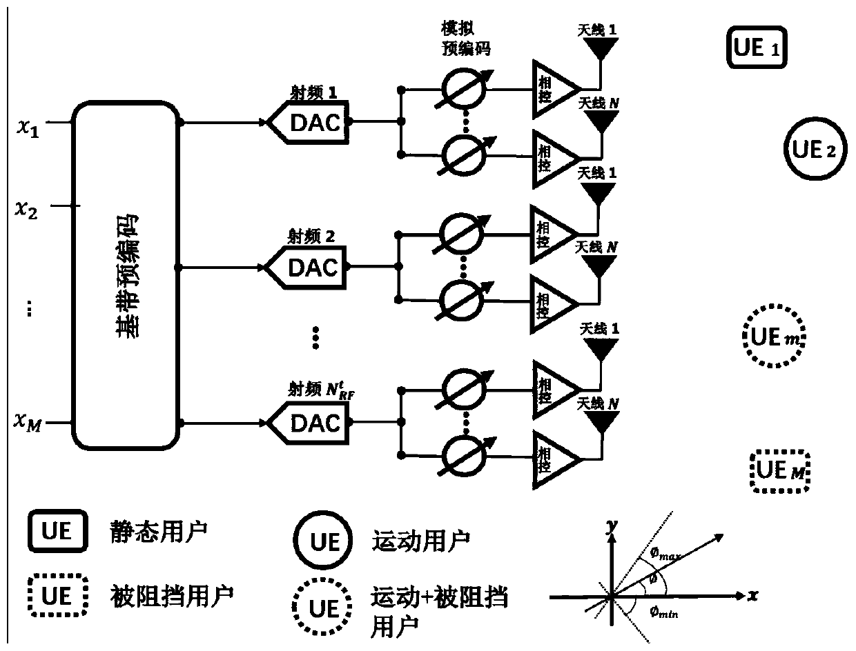
[0138] See figure 1 , figure 1 It is a system model diagram provided by the embodiment of the present invention. As shown in the figure, the millimeter wave communication system used in this embodiment is composed of the millimeter wave part connected to the antenna array base station, the transmission channel and the user. Base station has transmitting sub-arrays, each transmitting sub-array has N antennas, and the base station has a total of There are M users in the system, and each user has receiving sub-arrays, each transmitting sub-array has N antennas, and each user has root receiving antennas, where each antenna is independent of each other, and the distance between adjacent antennas is Each user state is random, including four states: static, moving, blocked, and blocked+moving.
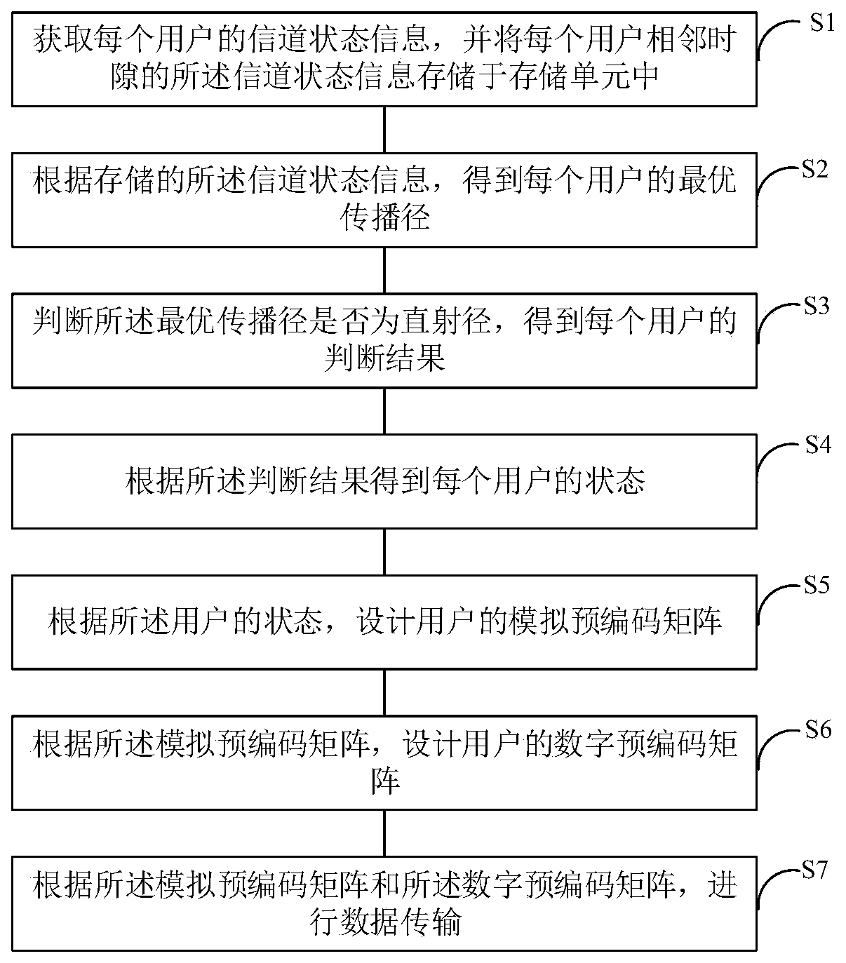
[0139] See figure 2 , figure 2 It is a flowchart of a method for dynamic user hybrid precoding of a millimeter wave system provided by an embodiment of the present invention. As...
Embodiment 2
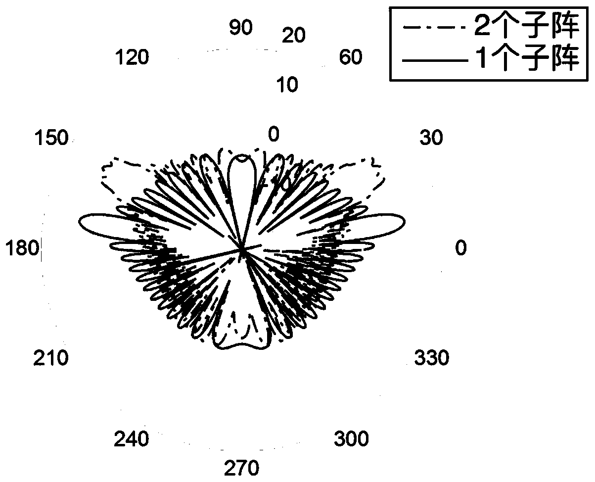
[0269] This embodiment is a simulation experiment of the method for dynamic mixed user precoding in the millimeter wave system in Embodiment 1. The simulation conditions of this embodiment are: the base station has 15 transmitting sub-arrays, each transmitting sub-array has 20 antennas, there are 5 users in the system, each user has 3 receiving sub-arrays, and each receiving sub-array has 20 antennas. root antenna, the Rice factor K is 7dB, and the transmitted power of each signal is unit power.
[0270] See image 3 with Figure 4 ,in, image 3 For adopting the method of the present invention and adjacent cooperative sub-arrays are N c = 2 and the contrast figure of the beam pattern figure that does not adopt the method of the present invention; Figure 4 For adopting the method of the present invention, the adjacent cooperative sub-matrix is N c = 2 and N c = 3 beam pattern diagram comparison chart. Such as image 3 shown, using N c =2 The beam of the inventive me...
PUM
 Abstract
Description
Claims
Application Information
 - R&D
- Intellectual Property
- Life Sciences
- Materials
- Tech Scout
- Unparalleled Data Quality
- Higher Quality Content
- 60% Fewer Hallucinations
Browse by: Latest US Patents, China's latest patents, Technical Efficacy Thesaurus, Application Domain, Technology Topic, Popular Technical Reports.
© 2025 PatSnap. All rights reserved.Legal|Privacy policy|Modern Slavery Act Transparency Statement|Sitemap|About US| Contact US: help@patsnap.com


