Working surface profile line of a U-forming machine mold and its generation method

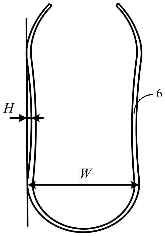
A forming machine and working surface technology, applied in the field of steel pipe manufacturing, can solve problems such as out-of-roundness exceeding the standard, indentation on the surface of the steel plate, and the side wall depression H of the U-shaped cylinder 6 exceeding the standard, etc.

Active Publication Date: 2021-06-15
BAOSHAN IRON & STEEL CO LTD
View PDF8 Cites 0 Cited by
  • Summary
  • Abstract
  • Description
  • Claims
  • Application Information

AI Technical Summary

Problems solved by technology

However, the molding lines of the working surface of the existing U-forming machine molds are all circular. When it is necessary to produce thin-walled steel pipes, the sidewall dent H of the U-shaped cylinder 6 will exceed the standard, the surface of the steel plate will have indentations, and the out-of-roundness will exceed the standard, etc. problem, need to repeat the U-forming process many times

Method used


Image

  • Working surface profile line of a U-forming machine mold and its generation method
  • Working surface profile line of a U-forming machine mold and its generation method
  • Working surface profile line of a U-forming machine mold and its generation method

Examples


Embodiment Construction

[0025] Below, the structure and working principle of the present invention will be further described in conjunction with the accompanying drawings.

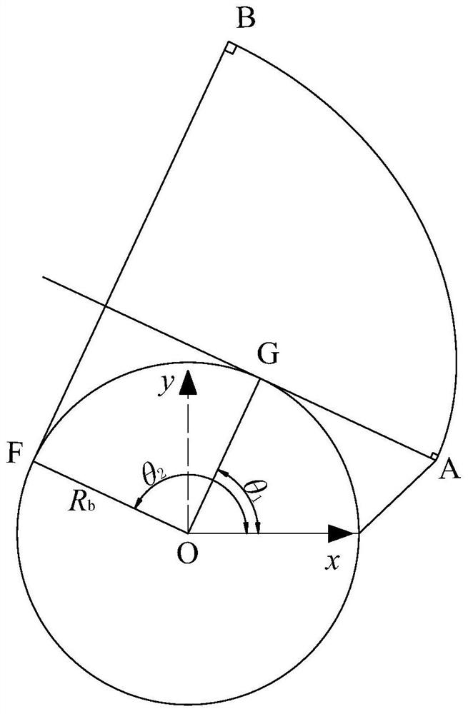
[0026] see figure 2 , the profile line of the working surface of the mold of the U forming machine of the present invention is symmetrical about the center line BF, and the profile line on one side of the center line BF includes an involute segment BA and an arc segment AC, and the involute segment BA and the arc segment AC are smoothly connected , that is, the radius of curvature at the junction point A of the two is the same; correspondingly, the profile line on the other side of the center line BF includes the involute segment BD and the arc segment DE, and the involute segment BD and the arc segment DE are smoothly connected, that is The radius of curvature at the junction point D of the two is the same.

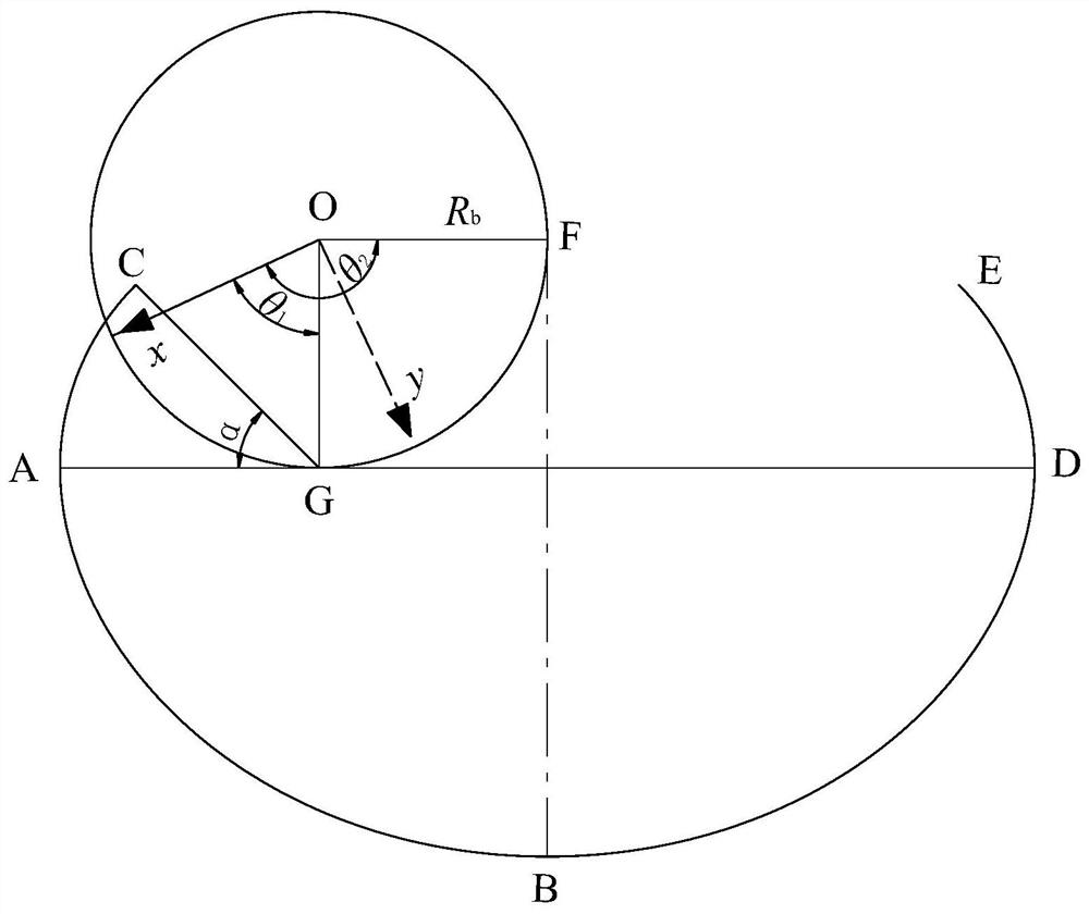
[0027] see image 3 , establish a Cartesian coordinate system with the center O of the base circle as the origin, and ...


PUM


Abstract

The invention discloses a profile line of the working surface of a mold of a U forming machine. The profile line is symmetrical about the center line, and the profile line on one side of the center line includes an involute segment and an arc segment. The involute segment and the arc segment The arc segments are connected smoothly. The invention also discloses a method for generating the mold line of the working surface of the mold of the U forming machine. By adopting the profile line of the working surface of the mold of the U forming machine of the present invention, the mold can complete the U forming of the thin steel plate at one time.

Description

technical field [0001] The invention relates to the field of steel pipe manufacturing, in particular to a molding line of a mold working surface of a U forming machine and a method for generating the same. Background technique [0002] Longitudinal submerged arc welded pipes are welded pipes made of steel plates through different forming processes. According to the forming methods, they are divided into UOE, JCOE, RBE, CFE, PFE, etc. The UOE forming method is to first press the pre-bent steel plate into a U shape in the forming die of the U forming machine, then press it into an O shape in the forming die of the O forming machine, weld it into a tube blank and then expand the overall diameter, and finally After water pressure, non-destructive testing, and chamfering, it becomes a finished pipe. [0003] figure 1 It is the ideal state diagram that the pre-bending steel plate is pressed into U-shaped cylinder 6 for U forming machine. The sidewall depression H of the U-shape...

Claims


Application Information

Patent Timeline
Patent Type & Authority Patents(China)
IPC IPC(8): B21D5/02
CPCB21D5/0209
Inventor 李新文王啸修郭运谢仕强郭胜吴毅文
Owner BAOSHAN IRON & STEEL CO LTD
Why Eureka
Try Eureka