

A piezoelectric micropump
A micro-pump and piezoelectric technology, applied in the direction of pumps, pump components, variable capacity pump components, etc., can solve the problems of large reverse leakage, affecting the output flow and output pressure of the pump, and insufficient air tightness, etc., to achieve improved Output pressure, simple structure, and the effect of improving output capacity
Active Publication Date: 2022-05-31
CHONGQING UNIV
View PDF17 Cites 0 Cited by
- Summary
- Abstract
- Description
- Claims
- Application Information
AI Technical Summary
Problems solved by technology
However, most of the reported micropump valve structures have only one layer of polymer film, the airtightness is not good enough, and the reverse leakage is large, which affects the output flow and output pressure of the pump.
Method used
View moreImage
Smart ImageViewing Examples

Examples
Embodiment Construction
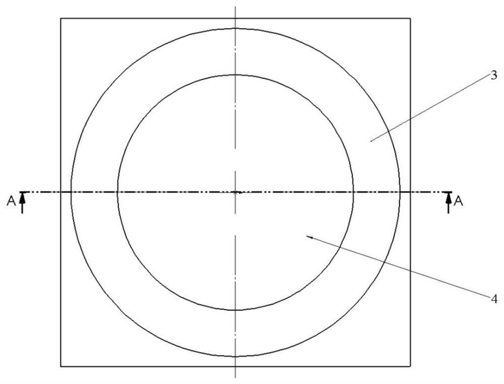
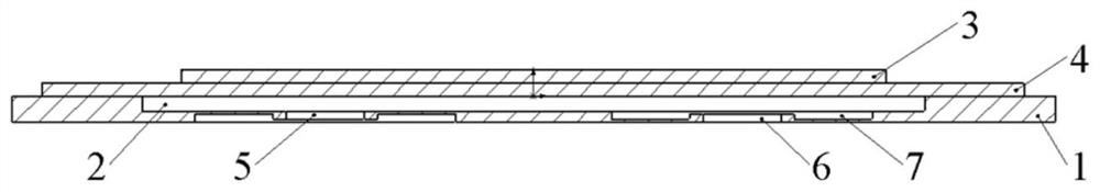
[0020] Referring to FIG. 1 and FIG. 2, the piezoelectric micropump can be divided into an upper structure and a lower structure. The superstructure mainly includes piezoelectric
Login to View More PUM
 Abstract
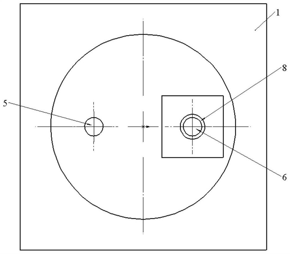
The invention protects a piezoelectric micropump, which includes a piezoelectric vibrator, a magnetic composite microvalve and a pump body. The magnetic composite microvalve includes a magnetic composite diaphragm and a support beam. The magnetic composite diaphragm consists of a polymer material layer on the surface, The flexible material layer of the bottom layer and the magnetic material layer of the middle layer are compounded, and the magnetic composite microvalve is respectively supported by the support beam and located above the pump inlet and the pump outlet of the pump body; magnetic suction is set on the pump inlet and the pump outlet. The inlet and outlet are closed by the suction force of the magnetic suction ring and the magnetic composite microvalve. The invention adopts a multi-layer magnetic composite microvalve, which can improve the airtightness of the micropump, prevent reverse leakage and increase the output pressure of the micropump.
Description
A piezoelectric micropump technical field [0001] The invention belongs to the field of microfluidic control, in particular to a microfluidic pump. Background technique As the core control element in the microfluidic system, the micropump plays an important role in drug delivery, synthesis, microfluidic supply and precise Control and other fields have broad application prospects. [0003] At present, most of the research on micropumps at home and abroad is based on piezoelectric thin film pumps driven by piezoelectric wafers. Piezo Film Pump It is mainly composed of piezoelectric vibrator, pump valve and pump body. During operation, alternating current is applied to both ends of the piezoelectric vibrator, and the voltage is pressed under the action of the electric field. The electric vibrator produces radial compression, and stress is generated inside the cavity, which causes the piezoelectric vibrator to bend and deform. When the piezoelectric vibrator is bent forw...
Claims
Login to View More Application Information
Patent Timeline
 Patent Type & AuthorityPatents(China)
IPC IPC(8): F04B43/04F04B53/10F04B53/00
CPCF04B43/046F04B43/0054F04B53/102F05C2225/10F05C2225/02F05C2225/00
Inventor陈李李丹阳贾青青张志强
OwnerCHONGQING UNIV