
Cement plant desulfurization and denitrification waste gas treatment apparatus

A waste gas treatment device, desulfurization and denitrification technology, which is applied in gas treatment, dispersed particle separation, membrane technology, etc., can solve the problems of unreasonable design of waste gas desulfurization, reduction of waste gas desulfurization efficiency, and inability to evenly distribute waste gas, so as to improve the efficiency of waste gas desulfurization. , The effect of effectively improving the efficiency of waste gas desulfurization, improving the rationality and compactness of the structure design

Pending Publication Date: 2020-04-10
苏州仕净科技股份有限公司
View PDF0 Cites 8 Cited by
  • Summary
  • Abstract
  • Description
  • Claims
  • Application Information

AI Technical Summary

Problems solved by technology

[0004] Existing desulfurization and denitrification equipment often have problems such as unreasonable exhaust gas desulfurization design, uncompact structure, and low desulfurization efficiency. Only one desulfurization treatment can be performed on the exhaust gas entering the equipment
And because the exhaust gas usually flows in the equipment in a laminar state after entering the cylinder, the exhaust gas cannot be evenly distributed in the cylinder, which further reduces the efficiency of exhaust gas desulfurization

Method used


Image

  • Cement plant desulfurization and denitrification waste gas treatment apparatus
  • Cement plant desulfurization and denitrification waste gas treatment apparatus
  • Cement plant desulfurization and denitrification waste gas treatment apparatus

Examples


Embodiment Construction

[0038] The technical solutions of the present invention will be described in detail below through embodiments with reference to the accompanying drawings. It should be noted here that the descriptions of these embodiments are used to help understand the present invention, but are not intended to limit the present invention.

[0039] The term "and / or" in this article is just an association relationship describing associated objects, which means that there may be three relationships, for example, A and / or B, which can mean: A exists alone, B exists alone, and A and B exist simultaneously. In the three cases of B, the term " / and" in this article is to describe another associated object relationship, which means that there can be two relationships, for example, A / and B, which can mean: there is A alone, and there are two cases of A and B alone , In addition, the character " / " in this article generally indicates that the contextual objects are an "or" relationship.

[0040] accor...


PUM


Abstract

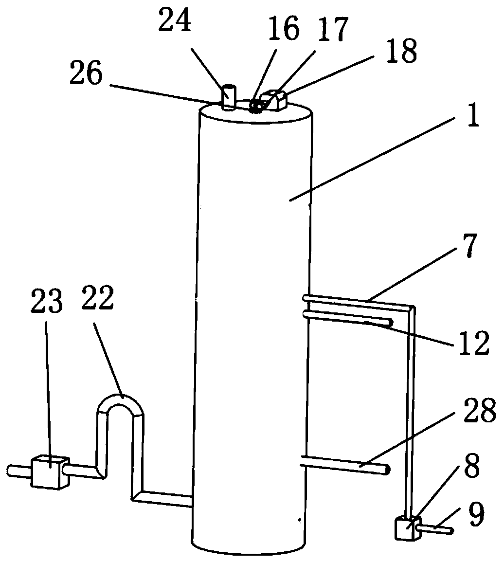
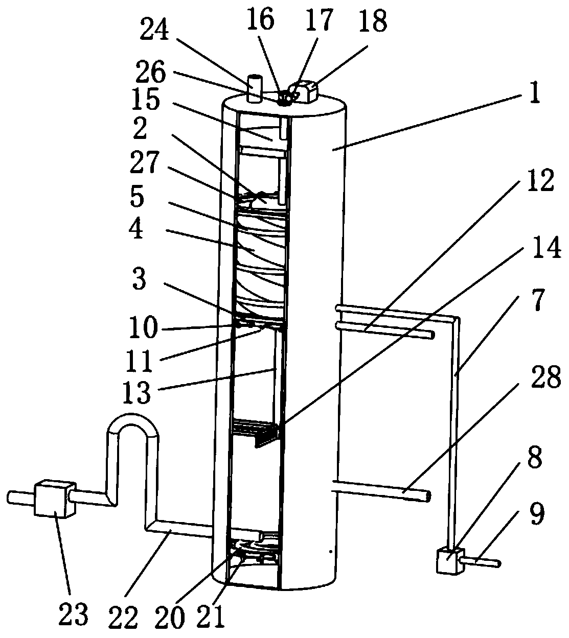
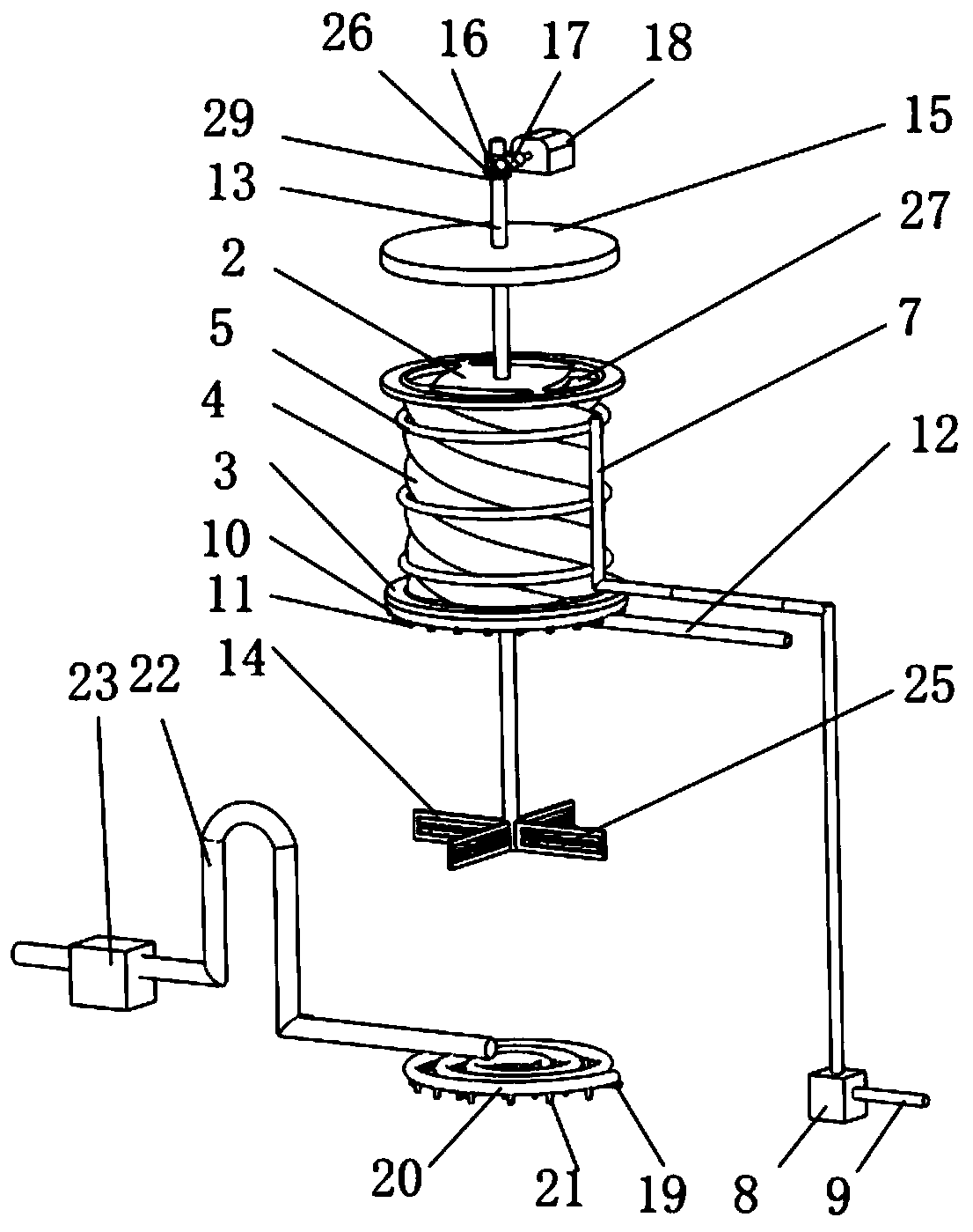
The present invention discloses a cement plant desulfurization and denitrification waste gas treatment apparatus, which comprises: a cylindrical body with two closed ends; a mist spraying showering part which comprises a mist spraying part and a showering part, wherein the mist spraying part is arranged on the cylinder body, and the showering part is arranged on the mist spraying part; a turbulentflow part which comprises a rotating rod, turbulent flow blades, a demister and a rotating power piece, wherein the rotating rod and the rotating power piece are both arranged on the cylinder body, and the turbulent flow blades and the demister are both arranged on the rotating rod; a preliminary desulfurization part which comprises a gas transmission fixing frame, a gas transmission pipe, a gastransmission nozzle and a waste gas input pipe, wherein the gas transmission fixing frame is arranged on the cylinder body, the gas transmission pipe is arranged on the gas transmission fixing frame,the gas transmission nozzle is arranged on the gas transmission pipe, and the waste gas input pipe is connected with the gas transmission pipe. The cement plant desulfurization and denitrification waste gas treatment apparatus is reasonable in structural design, and can perform multiple different forms of desulfurization treatment on waste gas; and the waste gas is converted into a turbulent flowstate from a laminar flow state, so that the waste gas can be uniformly distributed in the cylinder body, and the desulfurization efficiency can be effectively improved.

Description

technical field [0001] The invention relates to the technical field of waste gas treatment, and more specifically, the invention relates to a waste gas treatment device for desulfurization and denitrification in a cement plant. Background technique [0002] Waste gas treatment refers to the pretreatment of waste gas generated in industrial sites and factory workshops before being discharged to the outside, so as to meet the national standards for external discharge of waste gas. General waste gas treatment includes organic waste gas treatment, dust waste gas treatment, acid-base waste gas treatment, odor waste gas treatment and air sterilization, disinfection and purification. [0003] SO 2 , NO X It is the most influential pollutant in air pollution, which is extremely harmful to human body, environment and ecological system. With the increasingly stringent environmental protection requirements, SO 2 , NO X The problem of emission is getting more and more attention, es...

Claims


Application Information

Patent Timeline
IPC IPC(8): B01D53/78B01D53/50B01D53/56B01D53/75
CPCB01D53/78B01D53/50B01D53/56B01D53/75B01D2258/0233
Inventor 董仕宏吴倩倩张世忠
Owner 苏州仕净科技股份有限公司
Learn More