Glue filling auxiliary equipment for LED guardrail pipe
A technology of LED guardrail tubes and auxiliary equipment, which is applied in the direction of coating and liquid coating devices on the surface, etc., which can solve the problems of excessive height and inability to prevent the glue layer, so as to reduce operation steps, improve equipment practicability, and avoid pouring The effect of high glue height
- Summary
- Abstract
- Description
- Claims
- Application Information
AI Technical Summary
Problems solved by technology
Method used
Image
Examples
Embodiment 1
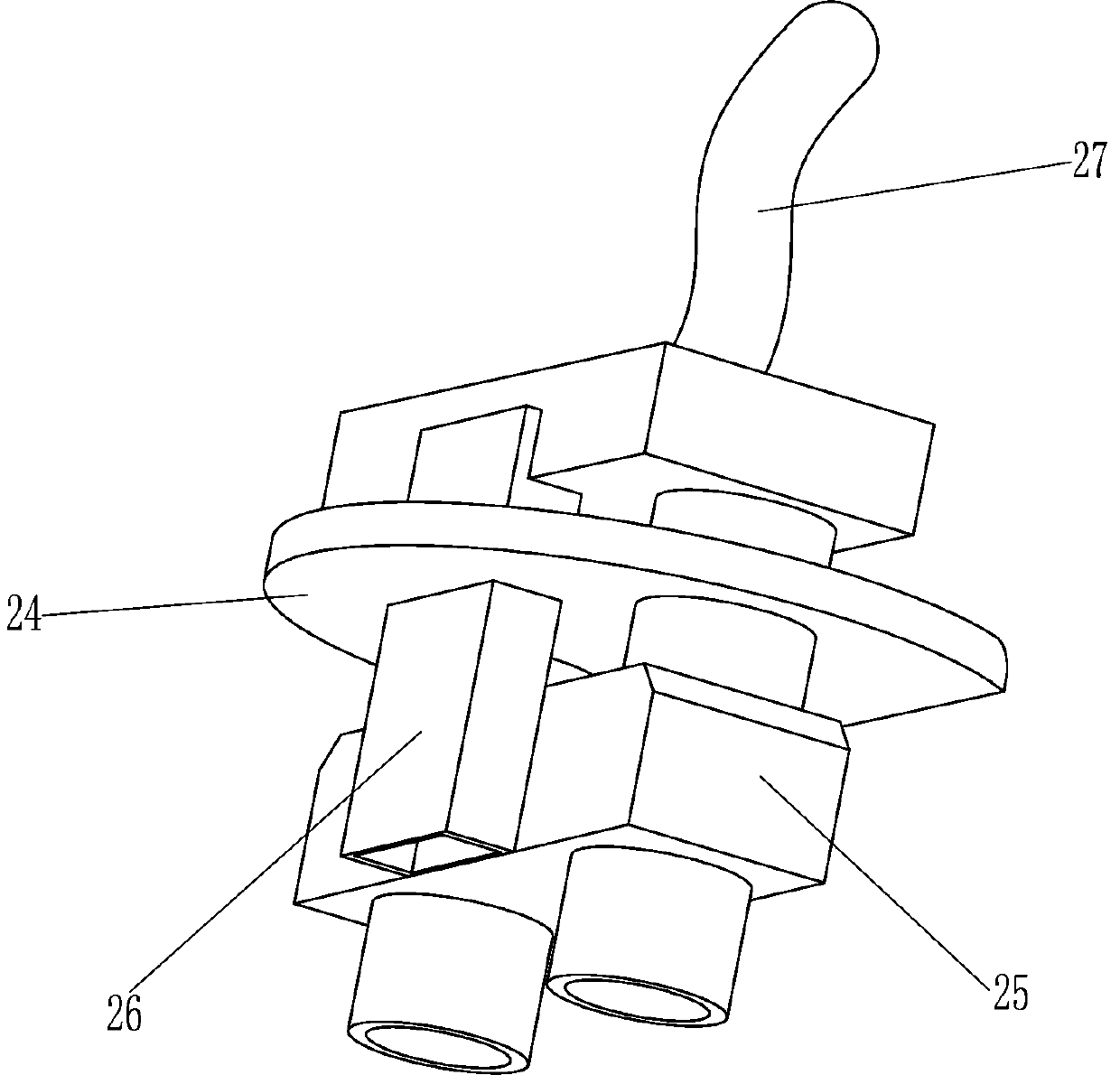
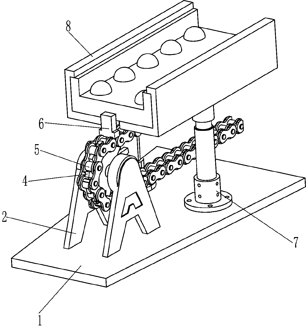
[0024] A LED guardrail tube glue filling auxiliary equipment, such as Figure 1-6 As shown, it includes a bottom plate 1, a first mounting seat 2, a second mounting seat 3, a sprocket 4, a chain 5, a push block 6, a support column 7, an asymmetrical I-shaped plate 8, and a first symmetrical I-shaped plate 9. Second symmetrical I-shaped plate 10, concave opening plate 11, biaxial drive motor 12, first drive assembly 13, drive gear 14, guide sleeve 15, guide rod 16, first compression spring 17, rack 18 , wedge-shaped plate 19, the third mounting seat 20, mounting frame 21, sliding sleeve 22, pushing mechanism 23, horizontal plate 24, double nozzle nozzle 25, strip nozzle 26 and infusion tube 27, the bottom plate 1 top side is provided with the first A mounting base 2, a second mounting base 3 is provided on the other side of the top of the bottom plate 1, a sprocket 4 is rotatably connected to the second mounting base 3 and the first mounting base 2, and chains are wound around ...
Embodiment 2
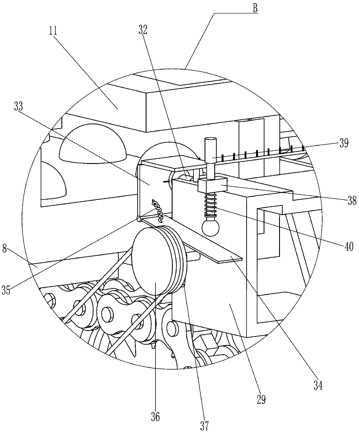
[0028] On the basis of Example 1, such as Figure 4-5 As shown, it also includes a support seat 28, a scraper frame 29, a rotating assembly 30, a scraper head 31, a single-axis drive motor 32, a mounting plate 33, a sloping plate 34, and a torsion spring 35, and the rear asymmetrical I-shaped plate 8 A support seat 28 is provided on the support seat 28, and a scraper frame 29 is arranged on the support seat 28. A rotating assembly 30 is provided on one side of the scraper frame 29, and a plurality of scraper heads 31 are evenly distributed on the rotating assembly 30. The top of the scraper frame 29 A uniaxial drive motor 32 is provided, the output shaft of the uniaxial drive motor 32 is connected to the rotating assembly 30, the top of the scraper frame 29 is provided with a mounting plate 33, and the bottom of the mounting plate 33 is rotatably connected to a slant plate 34, and the slant plate 34 is connected to the mounting plate 33 is connected with torsion spring 35.
...
Embodiment 3
[0031] On the basis of Example 2, such as Figure 4-5 As shown, it also includes a second drive assembly 36 and a cam 37, the support base 28 is rotatably connected with a second drive assembly 36, the lower part of the second drive assembly 36 is connected with the transmission shaft of the second mount 3, the second drive assembly 36 tops are provided with cam 37.
[0032] When the equipment is in normal operation, the transmission shaft on the second mounting base 3 drives the second driving assembly 36 to rotate, and then drives the cam 37 to rotate, and through the cooperation of the cam 37 and the swash plate 34 and the upper device, the swash plate 34 swings repeatedly, It is convenient to quickly shake off the glue particles on the surface of the swash plate 34 to prevent it from sticking to the slant plate 34 .
[0033] Such as Figure 5 As shown, it also includes a mounting block 38, a knock bar 39 and a second compression spring 40. The top of the scraper frame 29...
PUM
 Abstract
Description
Claims
Application Information
 - R&D
- Intellectual Property
- Life Sciences
- Materials
- Tech Scout
- Unparalleled Data Quality
- Higher Quality Content
- 60% Fewer Hallucinations
Browse by: Latest US Patents, China's latest patents, Technical Efficacy Thesaurus, Application Domain, Technology Topic, Popular Technical Reports.
© 2025 PatSnap. All rights reserved.Legal|Privacy policy|Modern Slavery Act Transparency Statement|Sitemap|About US| Contact US: help@patsnap.com


