Part additive composite manufacturing device and method

A technology of manufacturing device and control device, applied in the field of additive manufacturing, can solve the problems of poor surface roughness of parts, inability to achieve near net shape of parts, and inability to solve the problem of inner surface polishing of parts, so as to improve efficiency, avoid secondary strengthening and other problems. processing effect

Inactive Publication Date: 2020-04-10
CHANGAN UNIV +1
View PDF14 Cites 12 Cited by
  • Summary
  • Abstract
  • Description
  • Claims
  • Application Information

AI Technical Summary

Problems solved by technology

In the process of laser additive manufacturing and the composite manufacturing process of laser additive manufacturing and laser peening, the common problem is that the surface roughness of the parts is poor, and the inner surface of the parts with complex inner runners and cavities cannot be polished. Solve, so the processed parts are difficult to meet the requirements of the industrial standard at one time, and secondary processing is required, and the near-net shape of the parts processing cannot be realized
[0005] Existing additive manufacturing devices can only use one of the laser shock peening or laser polishing technologies, so the defects in the two technologies cannot be avoided

Method used


Image

  • Part additive composite manufacturing device and method

Examples


Embodiment Construction

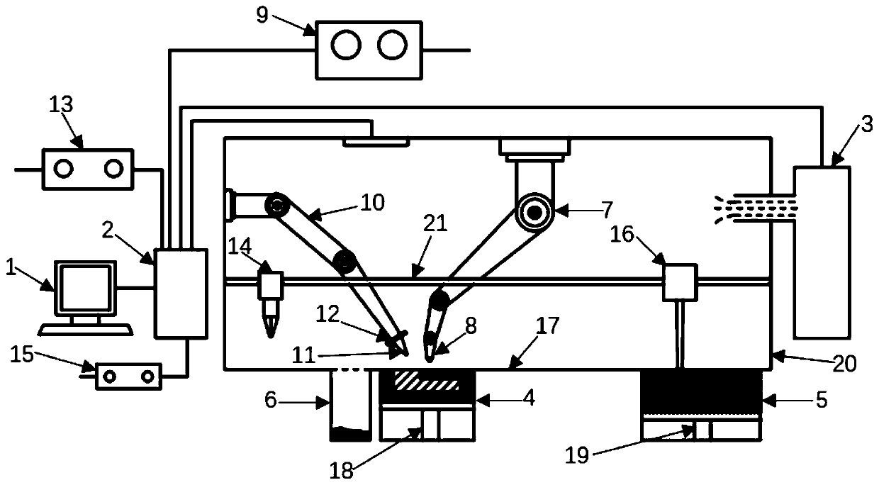
[0032] The present invention is described in further detail below in conjunction with accompanying drawing:

[0033] like figure 1 As shown, the parts additive composite manufacturing device described in the present invention includes a molding chamber 20, an inert gas source 3, a control device 2, a laser melting robot arm 7, a laser shot peening robot arm 10, a femtosecond laser emitter 14 and a molding Cylinder 4.

[0034] The molding chamber 20 is a closed chamber, and an inert gas source 3 is arranged in the molding chamber 20 , and the gas outlet of the inert gas source 3 is connected to the inside of the molding chamber 20 .

[0035]The laser melting mechanical arm 7 and the laser peening mechanical arm 10 are both arranged on the inner wall of the molding chamber 20. The moving track of the mechanical arm is realized by the operation of the control equipment. The end of the laser melting mechanical arm 7 is provided with a laser melting nozzle 8, and the laser peening...


PUM


Abstract

The invention discloses a part additive composite manufacturing device and method. The part additive composite manufacturing device comprises a forming chamber, a controlling device, a laser melting mechanical arm, a laser shot blasting mechanical arm, a femtosecond laser transmitter and a forming cylinder, wherein the bottom face of an inner cavity of the forming chamber serves as a working tabletop, the top of the forming cylinder is connected with the bottom of the working table top, a bottom plate of the forming cylinder is connected with a first lifting device, the laser melting mechanical arm and the laser shot blasting mechanical arm are both arranged on the inner wall of the forming chamber, a laser melting nozzle is arranged at the tail end of the laser melting mechanical arm, alaser shot blasting nozzle is arranged at the tail end of the laser shot blasting mechanical arm, an electric linear reciprocating mechanism is arranged in the inner cavity of the forming chamber, thefemtosecond laser transmitter is connected to the electric linear reciprocating mechanism, and the movement direction of the electric linear reciprocating mechanism is parallel to the working table top. The effect that three machining devices do not affect one another is realized, the comprehensive performance of produced parts is greatly improved, and meanwhile secondary machining is avoided.

Description

technical field [0001] The invention belongs to the field of additive manufacturing, and relates to a component additive composite manufacturing device and method. Background technique [0002] Additive manufacturing technology, also known as 3D printing technology, is a technology that uses digital models to gradually accumulate materials layer by layer with the help of printing equipment to manufacture solid parts. It has the characteristics of simple process and low cost. Laser selective melting, English Name: Selective Laser Melting, SLM, is one of the methods in additive manufacturing. This method is to design the three-dimensional solid model of the part on the computer, and then slice and layer the model to obtain the outline of a two-dimensional interface. data, and then generate a scan path from the contour data. Then use a high-energy laser beam to scan the pre-coated metal powder according to the scanning path, selectively melt it completely, and then cool and so...

Claims


Application Information

Patent Timeline
Patent Type & Authority Applications(China)
IPC IPC(8): B22F3/105B22F3/24B33Y30/00B33Y40/20
CPCB22F3/24B33Y30/00B33Y40/00B22F2003/247B22F10/00B22F10/36B22F10/32B22F12/222B22F12/43B22F10/25B22F12/90B22F10/28B22F10/50Y02P10/25
Inventor 袁战伟韩玉涛孙志平何光宇柴艳杨竹芳
Owner CHANGAN UNIV
Why Eureka
Try Eureka