
Patsnap Eureka
For R&D, Patsnap Eureka makes reading and utilizing patents & technical documents easy.
Patsnap Eureka AIR
Designed for self-driven R&D workflows. Generate viable solutions, solve complex R&D challenges, empower your innovation with AI.

Patsnap Eureka Materials
Designed for material experts only. Revolutionize your material R&D, from search, analyze, to developing new materials.

TechResearch
Generate reliable direction feasibility study reports for your R&D in just a few steps.

TechSeek
Discover and master advanced knowledge NOW. Basics, ideas, possibilities, all at once.

TechMind
As an expert in R&D Theories, TechMind can generates customized viable solutions instantly.

TechRisk
Analyze your overall solution with one click, know your potential R&D risks in advance.

TechMonitor
Get weekly tech updates, stay abreast of the latest tech innovations and key insights.
Clamping device for car ring-shaped part
A ring-shaped part and clamping device technology, which is applied in the field of automobile parts processing, can solve the problems of unsuitability for promotion, affecting the processing of ring-shaped parts, high price, etc., and achieves the effects of being easy to popularize and use, improving practicability and convenient use.
- Summary
- Abstract
- Description
- Claims
- Application Information
AI Technical Summary
Problems solved by technology
Method used
Image

Examples
Embodiment 1
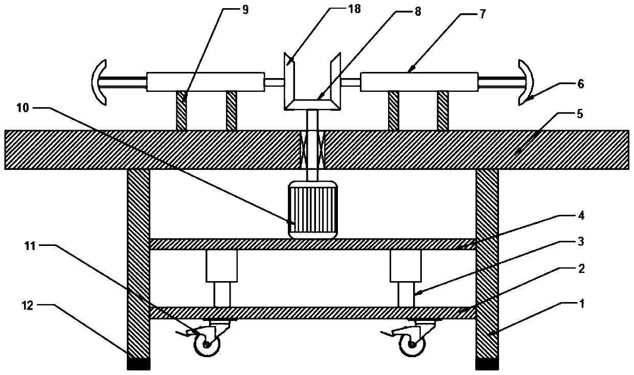
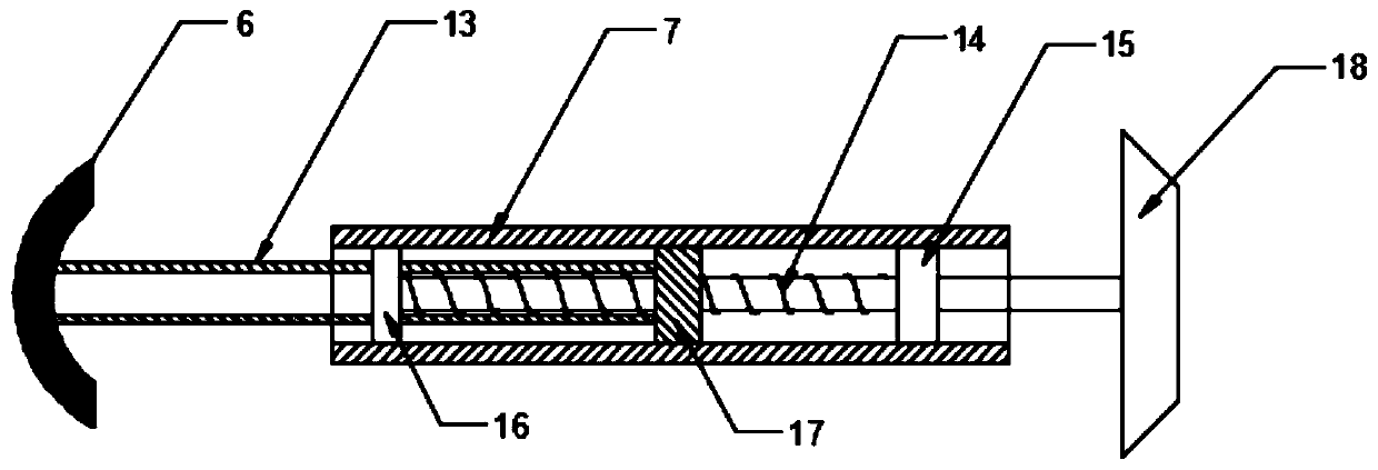
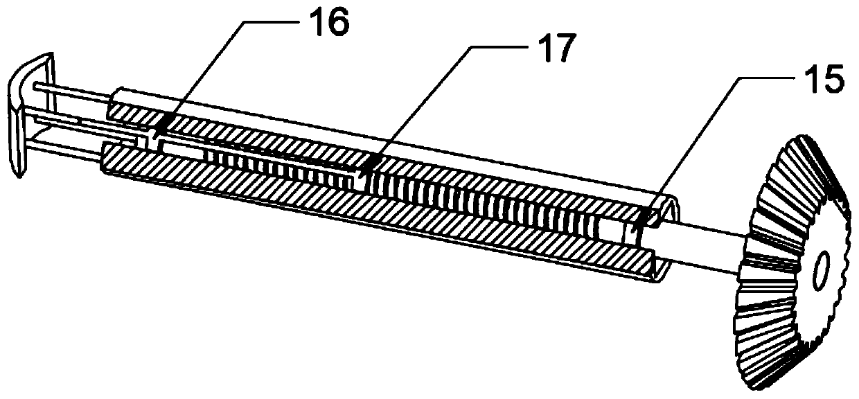
[0024] see Figure 1-3 , a clamping device for automotive ring parts, comprising a support column 1 and a processing table 5, the processing table 5 is fixedly welded on the support column 1, and several clamping assemblies are fixedly installed on the processing table 5, and the clamping assembly The specific type is not limited. In this embodiment, preferably, the clamping assembly includes an arc plate 6, a fixed sleeve 7, a fixed block 9, a push rod 13, a screw 14, a fixed bearing 15, a fixed plate 16, and a movable block. 17 and the second helical gear 18, a plurality of fixed blocks 9 are fixedly installed on the processing table 5, the fixed sleeve 7 is welded on the top of the fixed block 9, the movable block 17 is slidably installed on the inner wall of the fixed sleeve 7, and the fixed bearing 15 is fixedly installed on the One end of the fixed sleeve 7, the screw mandrel 14 is installed in the fixed bearing 15 and one end is fixedly connected with the second helical...
Embodiment 2
[0033] In order to increase the practicability of the device, this embodiment is further improved on the basis of Embodiment 1. The improvement is that a cylinder 3 is fixedly installed on the lower surface of the fixed plate 4, and the movable end of the cylinder 3 is connected with a movable plate 2, and the movable plate 2, some universal wheels 11 are installed. During use, the cylinder 3 works to push out the movable plate 2 downwards, and then the universal wheels 11 on the movable plate 2 are pushed out downwards to make it contact with the working ground, and the device is jacked up for easy movement. After the movement is completed, The cylinder 3 shrinks, and the movable plate 2 is pulled up, and then the universal wheel 11 is accommodated between the supporting columns 1, and the supporting columns 1 are in contact with the working ground, and then processed and used.
[0034] To sum up, by setting three sets of clamping components, the motor 10 drives the first hel...
PUM
 Abstract
Description
Claims
Application Information
 - R&D Engineer
- R&D Manager
- IP Professional
- Industry Leading Data Capabilities
- Powerful AI technology
- Patent DNA Extraction
Browse by: Latest US Patents, China's latest patents, Technical Efficacy Thesaurus, Application Domain, Technology Topic, Popular Technical Reports.
© 2024 PatSnap. All rights reserved.Legal|Privacy policy|Modern Slavery Act Transparency Statement|Sitemap|About US| Contact US: help@patsnap.com