A working method based on chip extraction mechanism during machine tool cutting operation

A cutting operation and working method technology, applied in the direction of manufacturing tools, metal processing equipment, metal processing machinery parts, etc., can solve the problems of reduced cutting accuracy of drill bits, scratches on the surface of metal parts, and stuck and damaged drill bits, etc., to prevent debris The effect of stuck damage, prevention of waste accumulation, safe and stable work

Active Publication Date: 2021-03-12
PAMA SHANGHAI MACHINE TOOL CO LTD
View PDF7 Cites 0 Cited by
  • Summary
  • Abstract
  • Description
  • Claims
  • Application Information

AI Technical Summary

Problems solved by technology

[0005] The purpose of the present invention is to provide a chip extraction mechanism based on the cutting operation of the machine tool, so as to solve the problem of the current metal workpiece processing machine tool proposed in the above-mentioned background technology. Wrapped on the drill bit, causing the waste chips to swing with the rotation of the drill bit, it is easy to scratch the surface of the metal parts. The cutting contact position of the workpiece is easy to cause the problem of the drill bit being stuck and damaged

Method used


Image

  • A working method based on chip extraction mechanism during machine tool cutting operation
  • A working method based on chip extraction mechanism during machine tool cutting operation
  • A working method based on chip extraction mechanism during machine tool cutting operation

Examples


Embodiment Construction

[0026] The following will clearly and completely describe the technical solutions in the embodiments of the present invention with reference to the accompanying drawings in the embodiments of the present invention. Obviously, the described embodiments are only some, not all, embodiments of the present invention. Based on the embodiments of the present invention, all other embodiments obtained by persons of ordinary skill in the art without making creative efforts belong to the protection scope of the present invention.

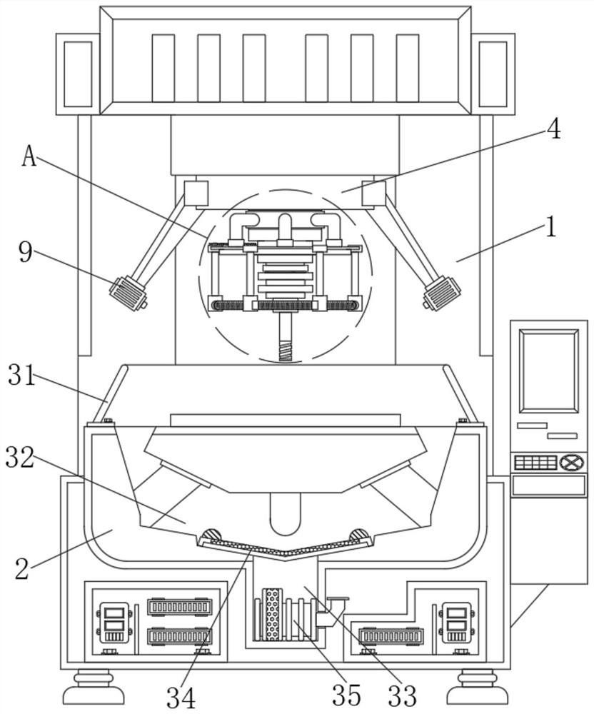
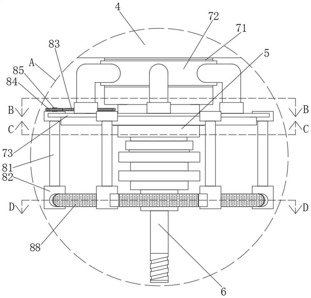
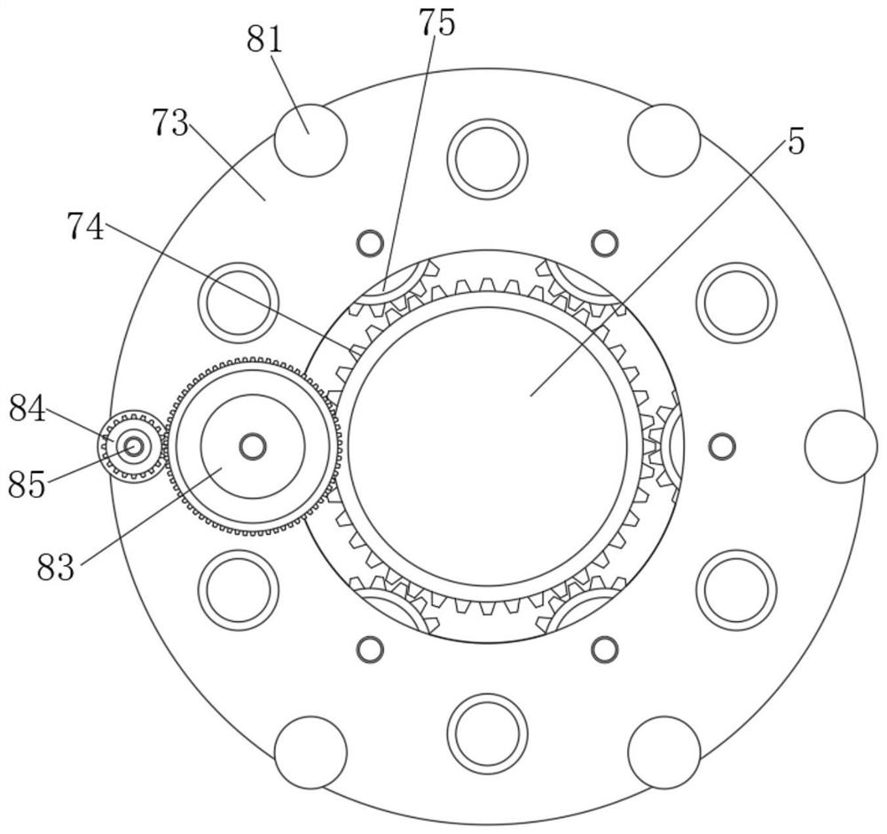
[0027] see Figure 1-7, an embodiment provided by the present invention: a chip extraction mechanism based on machine tool cutting operations, including a machine tool body 1 and a water pump 35, a processing platform 2 is fixedly installed below the machine tool body 1, and a processing platform 2 is installed inside the machine tool body The collecting mechanism, and the inside of the collecting mechanism includes a material retaining plate 31, and the mater...


PUM


Abstract

The invention discloses an operating method of a scrap leading-out mechanism based on machine tool cutting operation. The leading-out mechanism comprises a machine tool main body and a water pump, wherein a machining platform is fixedly installed below the machine tool main body, a collecting mechanism is installed in the machining platform, a telescopic main shaft is installed above the machine tool main body, a driving mechanism is installed on the outer side of the telescopic main shaft, the driving mechanism comprises a rotating disc, a rotating mechanism is installed on the rotating disc,and the rotating mechanism comprises rollers. According to the operating method of the scrap leading-out mechanism, a reversing gear in the driving mechanism is arranged for meshing transmission, sothat a lantern ring and a gear ring rotate in opposite directions, the rotating directions of a drill floor and the rotating disc are opposite, the rollers in the rotating mechanism at the lower partand a drill bit are driven to rotate reversely, through cooperation with miniature hook claws fixed to the outer sides of the rollers, one end of a long-strip-shaped waste scrap can be hooked when thewaste scrap flies out, the waste scrap is snapped or pulled open through reverse rotation, and the long-strip-shaped waste scrap is effectively prevented from flying and being wound on the drill bitfor a long time.

Description

technical field [0001] The invention relates to the technical field of machine tool debris extraction equipment, in particular to a working method based on a debris extraction mechanism during machine tool cutting operations. Background technique [0002] With the rapid development and progress of the national economy, the technology of the industrial manufacturing industry is also developing rapidly. More and more advanced technologies are introduced into the industrial manufacturing industry. As an important equipment in industrial manufacturing, machine tools are becoming more and more perfect in technological development. Existing machine tools can be divided into drilling machines and milling machines due to different cutting methods. [0003] When the drilling machine is in use, the drill bit is mainly used to move on the workpiece for processing. The drill bit and the metal workpiece are in a vertical state, so that the debris cut from the metal part is inconvenient t...

Claims


Application Information

Patent Timeline
Patent Type & Authority Patents(China)
IPC IPC(8): B23Q11/00
CPCB23Q11/00B23Q11/0042
Inventor 段芳利朱蕾袁福珍
Owner PAMA SHANGHAI MACHINE TOOL CO LTD
Why Eureka
Try Eureka